Thank you to RTL-SDR.com reader 'JJ' for writing in with a submission for his Lego Pi Radio. JJ's Lego Pi Radio consists of a Raspberry Pi and RTL-SDR and is designed to be an FM Radio, MP3 and internet radio player all in one, with a cute enclosure made out of Lego bricks. The radio is controlled by an external numpad which allows for a number of presets to be chosen from.
The internet radio and MP3 players are handled in software by VLC player and a script written by JJ is used to map the numpad to RTL-SDR FM presets, or MP3 and internet radio functions. The whole unit is run headless and if anything needs to be updated such as internet radio links, JJ simply accesses the unit via an SSH shell. JJ also writes how he had to try 3 different brands of speakers before he found one that could be driven directly from the Pi with adequate sound quality. In the future he hopes to add a bluetooth remote.
One problem that JJ found was that the standard rtl_fm did not produce high quality audio. Fortunately he found the NGSoftFM software which is capable of outputting high quality FM stereo sound and is compatible with RTL-SDR dongles.
In the past we've seen a similar project that was implemented on a BeagleBone Black. The idea in that project was to switch between FM and internet radio depending on the reception quality.
Thanks to OH2BNF for writing in and sharing his plan to build a "Large Scale Raspberry SDR" (LSR-SDR), which will be based on RTL-SDR dongles. To create the LSR-SDR he plans to take a 19" rack which can support up to 40 Raspberry Pi 3's, plus up to 160 USB devices, and turn it into a massive SDR array. The rack is key as it allows for simple power management of all the Pi's and other devices to be connected.
OH2BNF plans to connect 20 or so RTL-SDRs, with some operating individually and with others operating coherently via a common external oscillator. The rack may also contain some transceivers, an ICOM IC-7300, antenna switches, upconverters, LNAs and other hardware too. Once completed he hopes to move the system to a low RFI environment and operate the unit entirely remotely. With this he hopes to solve his local RFI issues. He also writes regarding applications:
Primary objectives are to incorporate automated adaptivity to the system at large – for example leveraging on band condition information, WSPR (Weak Signal Propagation Report) & friends, automated signal detection and decoding, great flexibility in terms of individual cluster nodes being able to fast respond to various needs and tasks, strong emphasis in parallel processing where applicable depending on the problem type and dataset, support for multiple end users benefiting from the computing and reception capacity of the cluster – to name the most significant.
It's an interesting idea for sure, and we hope to see some updates from OH2BNF in the future.
Thank you to YouTuber 'Tysonpower' who is known for making various RF related videos as he has recently reviewed our Triple Filtered ADS-B LNA on his blog and on YouTube. Note that his video is in German, but it contains English subtitles. In the review he compares our LNA against a more expensive ADS-B LNA and found that it performs just as good, if not better in some cases.
Our ADS-B LNA uses a triple filter design, as well as a two stage LNA which aims to significantly cut out interference from out of band signals which could overload the LNA and/or SDR dongle. It also has a low noise figure and high output gain of 27dB which is great for reducing losses on long runs of coax cable. More information about our LNA on the release post, and it can be purchased from our store.
Earlier in the month the International Space Station (ISS) was transmitting SSTV images down to the earth for anyone to receive an decode. The ISS does this several times a year to commemorate special space related events, such as the day Yuri Gagarin (first man in space) was launched.
In the video Thomas explains why the ISS does this, how to track the ISS, and then he demonstrates actually receiving and decoding the signal. Thomas uses an Airspy HF+ to receive the signal on 145.8 MHz, however an RTL-SDR could do the same job. For decoding he uses the MMSSTV software.
For new on when the ISS might transmit SSTV again, keep at eye on the ARISS Blog, and the ISS Ham Twitter page.
Recently a program called R820T2Tweak_Patched was released which is a GUI for GQRX that allows you to manually control not only the three RF gain settings on R820T2 RTL-SDRs, but also the four filter settings as well as the registers directly. The R820T2 is the most commonly found tuner chip on RTL-SDR dongles, and is generally considered the best for most applications.
The GUI could be useful for advanced users wanting to experiment with the various lower level R820T2 register settings, or for anyone that wants ultimate control over the filters in the RTL-SDR.
The software is based on the original R820Tweak which has the same features except the ability to control the registers directly.
R820Tweak_Patched GUI. Control Gain, Filters and Registers.
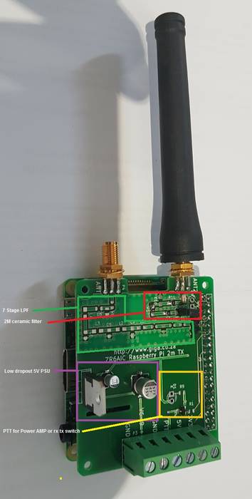
RPiTX is software that enables the Raspberry Pi to transmit any modulated signal over a wide range of frequencies using just a single GPIO pin. However, the transmission contains multiple harmonics and thus requires sufficient filtering in order to transmit legally within the 2M ham band. To solve this ZR6AIC uses a 2M Raspberry Pi Hat kit which he designed and created that contains two low pass filters as well at the option for an additional power amplifier.
The rest of ZR5AIC's post explains how his HAB telemetry system combines the Raspberry Pi 3, RPiTX 2M Hat, RTL-SDR, a GPS unit, battery, temperature sensor and optional camera into a full HAB transmitting system. He also explains the software and terminal commands that he uses which allows him to transmit via RPiTX a CW beacon and GPS and temperature sensor APRS telemetry data with the Direwolf software. Full instructions on setting up the alsa-loopback audio routing is also provided.
A few owners of our RTL-SDR V3 and/or our Triple Filtered ADS-B LNA (or other bias tee powered LNAs) have been having trouble getting the V3 bias tee to activate on the FlightAware PiAware Raspberry Pi image. The core stumbling point is that the PiAware image activates the dump1090 ADS-B decoder immediately upon boot. To activate the bias tee, the bias tee software requires access to the dongle which it cannot get since dump1090 is blocking it. So to get around this the bias tee must be activated first before dump1090 runs.
PiAware is FlightAware's Raspberry Pi image which feeds their flightaware.com flight tracking service using RTL-SDR dongles. By using our Triple Filtered ADS-B LNA, users can expect increased range and decoded messages, especially when using long runs of coax cable, and/or in environments with strong interfering signals.
In the instructions below we'll explain how to set up a PiAware image that automatically enables the Bias Tee upon boot.
Downloading the V3 Bias Tee Software onto PiAware
First we assume that you're starting fresh from a new PiAware image, so we need to enable WiFi and SSH connections which is part of the standard set up for PiAware. See the following links for instructions.
Download and install the RTL-SDR V3 Bias Tee software.
cd ~
git clone https://github.com/rtlsdrblog/rtl_biast
cd rtl_biast
mkdir build
cd build
cmake ..
make
Testing the Bias Tee
Over on his blog Akos has created a short guide to activating the bias tee manually, by first stopping dump1090, activating the bias tee, then restarting dump1090. It's a simple one line copy and paste job.
So after installing the rtl_biast software above you can use the following line to test the bias tee. After running this line the FlightAware service should be up and running again, with the bias tee and LNA activated.
sudo service dump1090-fa stop && cd ~/rtl_biast/build/src && ./rtl_biast -b 1 && sudo service dump1090-fa start
Automatically Starting the Bias Tee on Boot
Ideally we don't want to have to reactivate the bias tee manually every time the Raspberry Pi reboots. To make it automatic use the following instructions:
First create a service directory and configuration file
Finally press Ctrl+X then Y to close and save. Now whenever PiAware reboots the bias tee should be automatically activated as this service runs before dump1090 is activated.
Over on YouTube user Rob Fissel has uploaded a nice video that demonstrates the iBiquity HD Radio decoder working with an RTL-SDR. HD Radio is a terrestrial digital broadcast signal that is only used in North America. It is easily recognized by the two rectangular blocks on either side of a broadcast FM station signal on a spectrum analyzer/waterfall display.
For a long time it was thought impossible to decode due to the closed and proprietary nature of the signal format. But thanks to Theori who was able to reverse engineer and create an HD Radio decoder it has now become possible to decode this into actual audio that you can listen to. In some areas it is even possible to extract the weather and traffic data encoded into some broadcasts from iHeartRadio.
Rob's YouTube video demonstrates him downloading and setting up the HD Radio decoder, then receiving, decoding and listening to some HD Radio stations in his area.
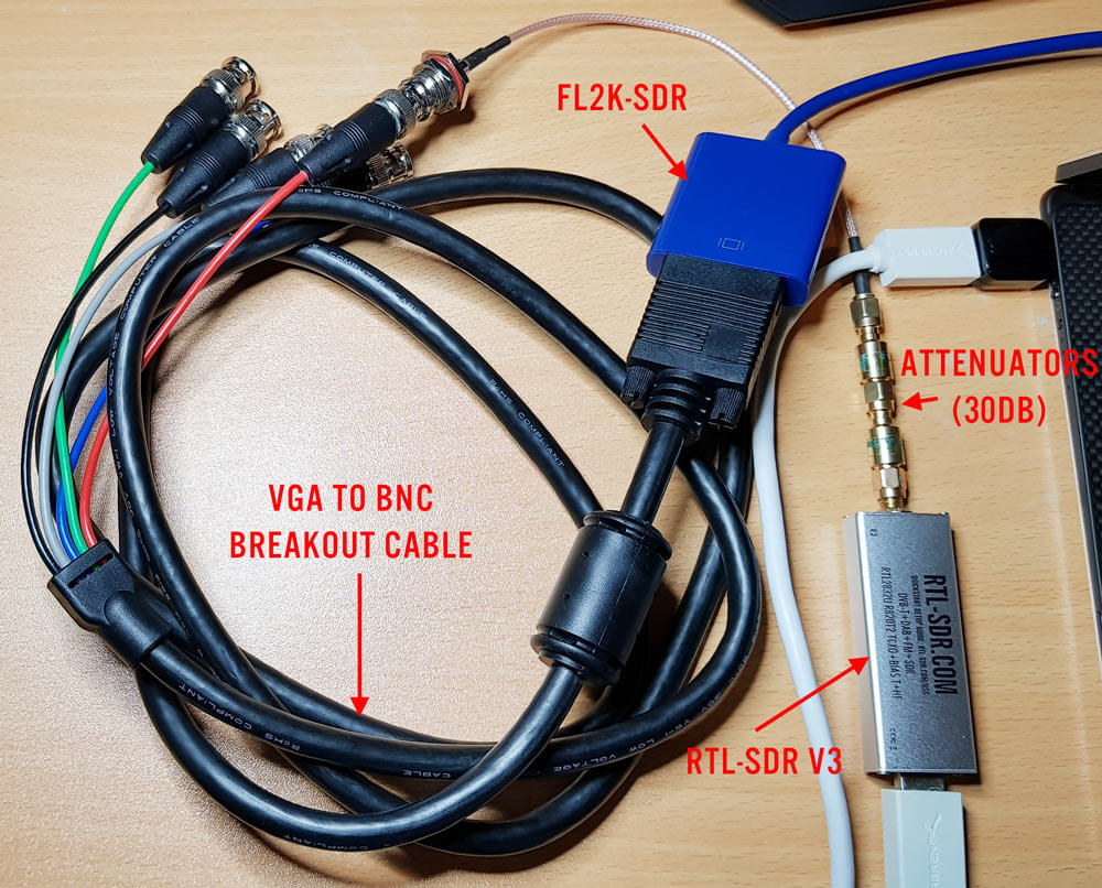
A few days ago we postedabout Osmo-FL2K, which is a newly released piece of software by Steve M from Osmocom that turns a common $5-$15 USB to VGA adapter into a transmit only capable SDR. It is very complimentary to the RTL-SDR.
Any USB to VGA adapter that contains a FL2K chip appears to be compatible and yesterday we received one and have been playing with it. This post is a demonstration of some of the results.
Hardware Used
The cheapest USB to VGA adapter found on the market. It seems all of the low cost $5 - $15 adapters that indicate "USB 3.0 to VGA", and max resolutions of 1920 x 1080 are compatible as they use the FL2K chip. More expensive units are not compatible. Compatible units all have a similar design (box at the end of a short USB cable, although there are other types too). The brand does not matter. (Amazon) (eBay) (Aliexpress)
A VGA to BNC breakout cable to connect the FL2K SDR directly to an RTL-SDR (via a BNC to SMA adapter) without illegally transmitting over the air. The Red color breakout is the one connected to the TX pin. (Amazon) (eBay) (Aliexpress)
A low cost 20dB or more attenuator to avoid overloading the dongle. (Amazon) (eBay) (Aliexpress)
FL2K Test Hardware
Setup
Note that you must have a USB 3.0 port to use Osmo-FL2K, although a USB 2.0 might work although at significantly reduced bandwidths.
Osmo-FL2K is Linux only at the moment, but it may be possible for someone to compile a Windows version, just like with RTL-SDR. Instructions for downloading and compiling the software are available on the official wiki. It is a standard git clone, cmake, make type procedure which can be done in 2 minutes. You'll also need to probably do an 'sudo apt-get install sox pv' if you want to run the WBFM example.
First we tried to boot into the GNU Radio Live Linux bootable image on a tablet like laptop that only has USB C 3.0 ports. Unfortunately while the FL2K-SDR was recognized, and Osmo-FL2K detected it, there was no signal coming out during test transmissions. It seems that there may be issues when a USB C to USB Type A converter is used.
Next we tried the GNU Radio Live Linux bootable image on a desktop PC and this time Osmo-FL2K worked fine when plugged into a USB 3.0 port. However, plugging it into extended ports seemed to cause it to not be detected. So if you're having trouble getting Osmo-FL2K to work, try other USB 3.0 ports on your PC, and avoid USB C adapters if possible.
We also tried Virtual Box, however the FL2K-SDR wouldn't connect to the Linux guest system, even though USB 3.0 was enabled and the extensions were installed. For VMWare it appears only that the paid versions support USB 3.0.
Testing
WBFM
Following the instructions on the official Osmo-FL2K page we were able to get an WBFM transmission up and running almost instantly. The provided example routes audio from your soundcard into the FL2K-SDR, causing it to transmit WBFM audio at 95 MHz. With this we were easily able to broadcast audio from YouTube to another PC via the FL2K-SDR although there is about two seconds of delay.
To choose the frequency you choose the carrier frequency and the sample rate, and then the transmit frequencies will be the sample rate +/- carrier frequency + harmonics.
FL2K broadcasting WFM with fl2k_fm.fl2k_fm help screen
Harmonics
Speaking of the harmonics we had a look at them using an Airspy and the SpectrumSpy software. The image below shows that the harmonics of a signal transmitted at 95 MHz extend all the way up to the maximum range of the Airspy at 1.8 GHz, and probably further. So filtering is very necessary if you ever want to transmit over the air.
Note that when broadcasting at 95 MHz (sample rate 130 MHz, carrier 35 MHz), there is also a strong signal at the carrier frequency. So band pass filtering would be required.
Harmonics when transmitting at 95 MHz
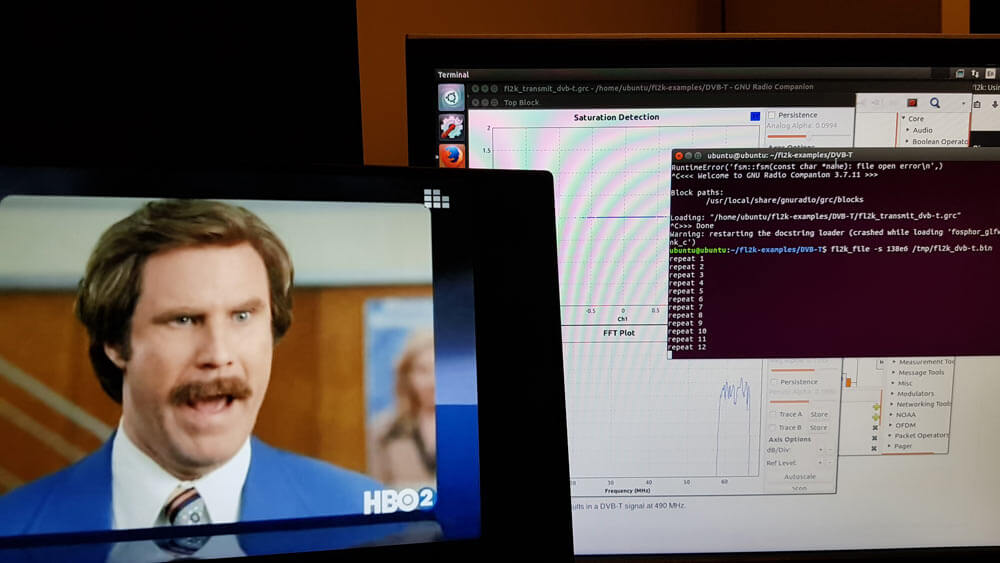
DVB-T
We also tested the DVB-T example found at https://github.com/steve-m/fl2k-examples, which worked flawlessly. By using the connected RTL-SDR dongle with the original DVB-T drivers we were able to receive a transmitted stream at 490 MHz using the ProgDVB software.
To do this follow the instructions in the fl2k-examples/DVB-T readme file to generate samples which Osmo-FL2K can transmit. Then on another PC install the DVB-T drivers for the RTL-SDR, and use ProgDVB to scan 490 MHz by manually editing the multiplexes options.
Osmo-FL2K transmitting DVB-T to a Laptop running an RTL-SDR.
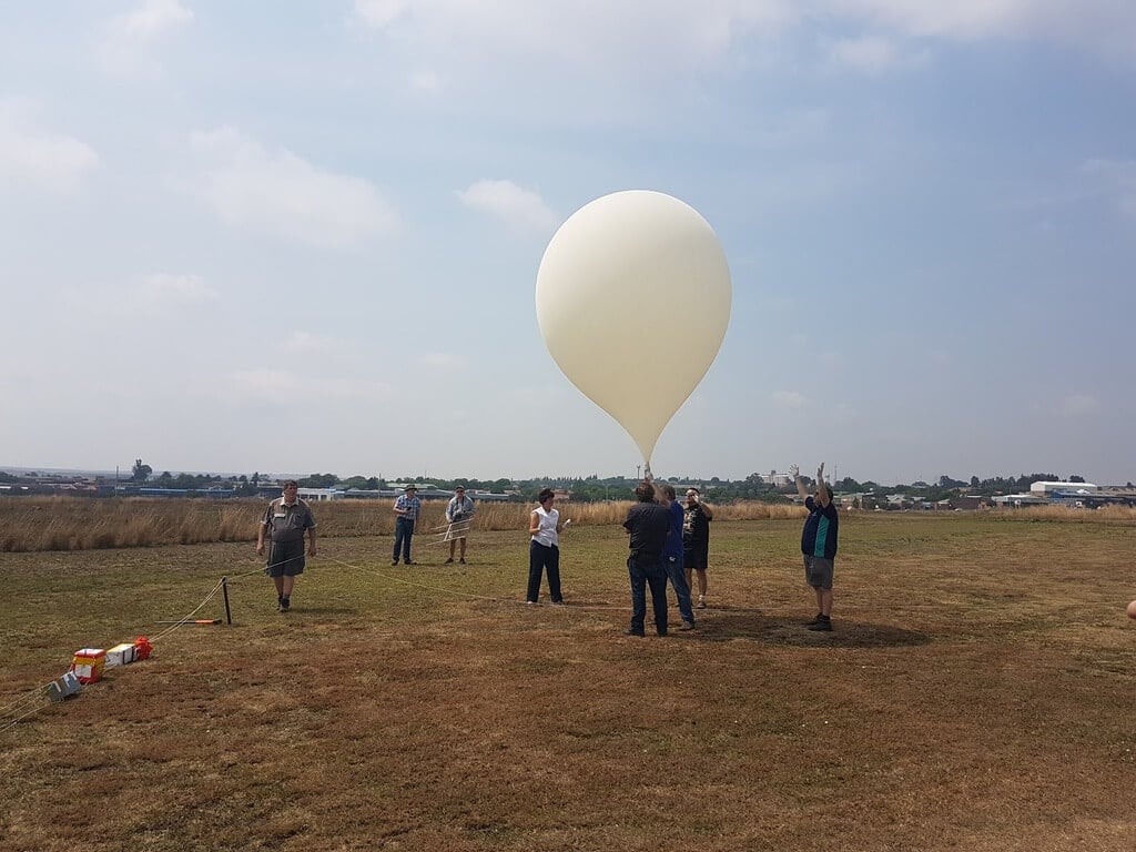
Radiosondes are light weight sensor packages that are attached to weather balloons. They transmit live RF weather telemetry down to earth as they rise. With an RTL-SDR and appropriate antenna it can be possible to decode this telemetry. One related hobby that a few people enjoy is radiosonde chasing, which is tracking and collecting radiosondes once they have fallen back to the earth. Some people collect them as trophies, and others like to repurpose them. For example in this previous post we've seen how some radiosondes can be repurposed into L-band antennas for RTL-SDR's.
Another way to repurpose radiosondes has recently been submitted to us by regular contributor 'happysat' who wrote in and let us know that it is actually possible to reprogram the commonly used Vaisala RS-41 radiosondes into being able to transmit ham radio APRS, RTTY or CW mode signals in the ISM or ham bands. The initial hack was first performed by SQ5RWU, and then OM3BC who managed to create easier to use software that could reflash the radiosondes internal firmware via the serial port on the radiosonde. This hack could be useful for any ham requiring a cheap transmitter for their own high altitude balloon experiments.
In addition to the above, happysat also wanted to mention his other radiosonde re-purposing project which was turning a DFM-06 and DFM-09 into a functional GPS unit that could be used for navigation when connected to a laptop, or to sync time on PCs.
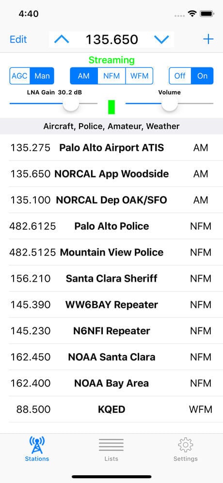
SDR Receiver, a new iOS app for RTL-SDR and Airspy HF+, is now available on the App Store. The app works with an RTL-SDR or Airspy HF+ that is attached to a host Mac, PC or Raspberry Pi running the rtl_tcp server or equivalent. The iOS device, which may be an iPhone or an iPad, communicates over the network with the host computer which may be anywhere on the network that is reachable by TCP/IP and that can sustain the required bandwidth.
SDR Receiver demodulates AM, narrowband FM and wideband FM signals. Key features include:
Easily entered and managed lists of stations to simplify station selection.
Adjustable squelch that works for both AM and FM signals.
Adjustable LNA gain for RTL-SDR.
Adjustable audio high pass and low pass filters.
Signal strength indicator that shows power level in the signal passband.
Multiple sampling rates down to 240Ksps for RTL-SDR.
Sampling rate of 768Ksps for Airspy HF+.
Streaming from an RTL-SDR requires installation of the librtlsdr package including the rtl_tcp utility on the host computer. Streaming from an Airspy HF+ requires installation of server software on the host computer that supports the Airspy HF+ and that streams data according to the protocol used by the rtl_tcp utility. One such server has been made available by Ron Nicholson in source code form on GitHub.
Requires an RTL-SDR or Airspy HF+, a host computer and server software which are not provided with the application.
Another RTL-SDR client for iOS is "RTL_TCP SDR" by Ron Nicholson which we posted about back in March when it was still in beta testing. RTL_TCP SDR includes a spectrum analyzer and FFT display. SDR Receiver appears to have no spectrum display, so is mostly useful for listening to preset frequencies, whilst RTL_TCP SDR appears to be more useful for spectrum exploring.
Programmer P. Lutus has recently released a new Python based software defined radio application that he calls "PLSDR". PLSDR is a full receiver, with spectrum and waterfall displays, a frequency manager, and support for multiple modes such as AM/FM/SSB/CW. Being Python based PLSDR supports both Linux and Windows. Compatible hardware includes the RTL-SDR, HackRF and SDRplay, however Lutus notes that he could only get the SDRplay working on Linux.
The PLSDR download page also contains various bits of information about the DSP math behind designing the SSB demodulator. Essentially he found that no online examples of GNU Radio based SSB demodulators were correctly implemented, so he decided to research and implement his own design. He also notes that PLSDR was designed by initially prototyping each function in GNU Radio first, before moving it over to Python. This approach allowed him to easily check his fundamental design before optimizing it for Python. If you are interested Lutus also has a very useful page dedicated to explaining the DSP basics behind SDRs.
PLSDR is fully open sourced and available on GitHub. Exploring the code may be a good way to learn about SDR concepts.
"RTL_TCP SDR" is a little different to "SDR Receiver" because it contains a full spectrum analyzer and waterfall display, whereas "SDR Receiver" only allows you to listen via presets or manual tuning. Both apps can not access the RTL-SDR directly on the iOS device due to Apple limitations. An external server on a Raspberry Pi or PC running rtl_tcp is required. Programmer HotPaw writes about his App:
An RTL-SDR Software Defined Radio receiver for iOS devices (requires an external rtl_tcp server). Listen to VHF AM and FM radio signals. View a waterfall of the RF spectrum. Connect, via the rtl_tcp network protocol, to a networked RTL-SDR USB peripheral.
iOS devices do not currently support the direct connection of USB devices such as an RTL-SDR. Thus, the use of this app requires network access to a server, such as a Raspberry Pi (or Mac), with an RTL-SDR unit plugged into its USB port, and running the rtl_tcp protocol at an TCP/IP network address accessible from your iOS device. The Raspberry Pi acts, essentially, as a USB port adapter for your iOS device.
No support is provided for installing any of the software needed to use this app with a Raspberry Pi. Please do not download this app unless you are already familiar with Software Defined Radio, have an RTL-SDR USB device, and have already installed and tested rtl_tcp on your Raspberry Pi, Mac, or other server.
Since Apple's iOS doesn't allow an RTL-SDR to be plugged directly into a Lightning port (even with a USB adapter), an rtl_tcp adapter, such as a Raspberry Pi (or Pi Zero) server is required.
This app is an experiment in real-time DSP and SDR coding using Apple's Swift and Metal GPU-shader programming languages. It includes a spectrum waterfall, and supports demodulating FM, AM, and SSB. Also, includes beta test support for the AirSpy HF+.
The Freqshow software is an RTL-SDR compatible tool for Raspberry Pi devices that can render live spectrum and waterfall displays. It is designed to run on portable touchscreens that plug into the Raspberry Pi. We've posted about freqshow a few times in the past.
The additional features are many. Additional features include: Full resolution zooming, I and Q Swap, 9 different pre FFT windowing functions to choose from. Center frequency offset or shift. PPM correction for the RTL2832. FFT averaging or FFT peaking. Easy frequency up and down from main screen. Easy Scale adjustment from main screen.
On YouTube he's also posted a video that demonstrates the software in action when running on an Adafruit 2.8" and Pi Foundation 7" TFT capacitive touch screen. Dan uses the software as a panadapter for his ham radio.
Over on YouTube Debashish Sahu has uploaded a video showing how he uses an RTL-SDR to capture and decode consumption data from his home electric/gas/water utility meters. He uses the rtl_amr software which already supports a wide range of meters such as Debashish's gas meter. Later in the video he shows a Python script that he's written which continuously grabs the data from rtl_amr, and passes it into the Home Assistant software using JSON. Then in Home Assistant the data is graphed, and he is able to determine points of interest, such as when appliances turned on or off.
Using RTL-SDR to read values from wireless electric/gas/water meters
This is an excerpt from our book on RTL-SDR which we've decided to post given that many new users struggle to understand all the settings in SDR#.
SDR# is currently the most popular SDR program used with the RTL-SDR. It's easy to set up and use. To install SDR#, go through our Quickstart Guide. Below we explain some of the settings and displays in SDR#.
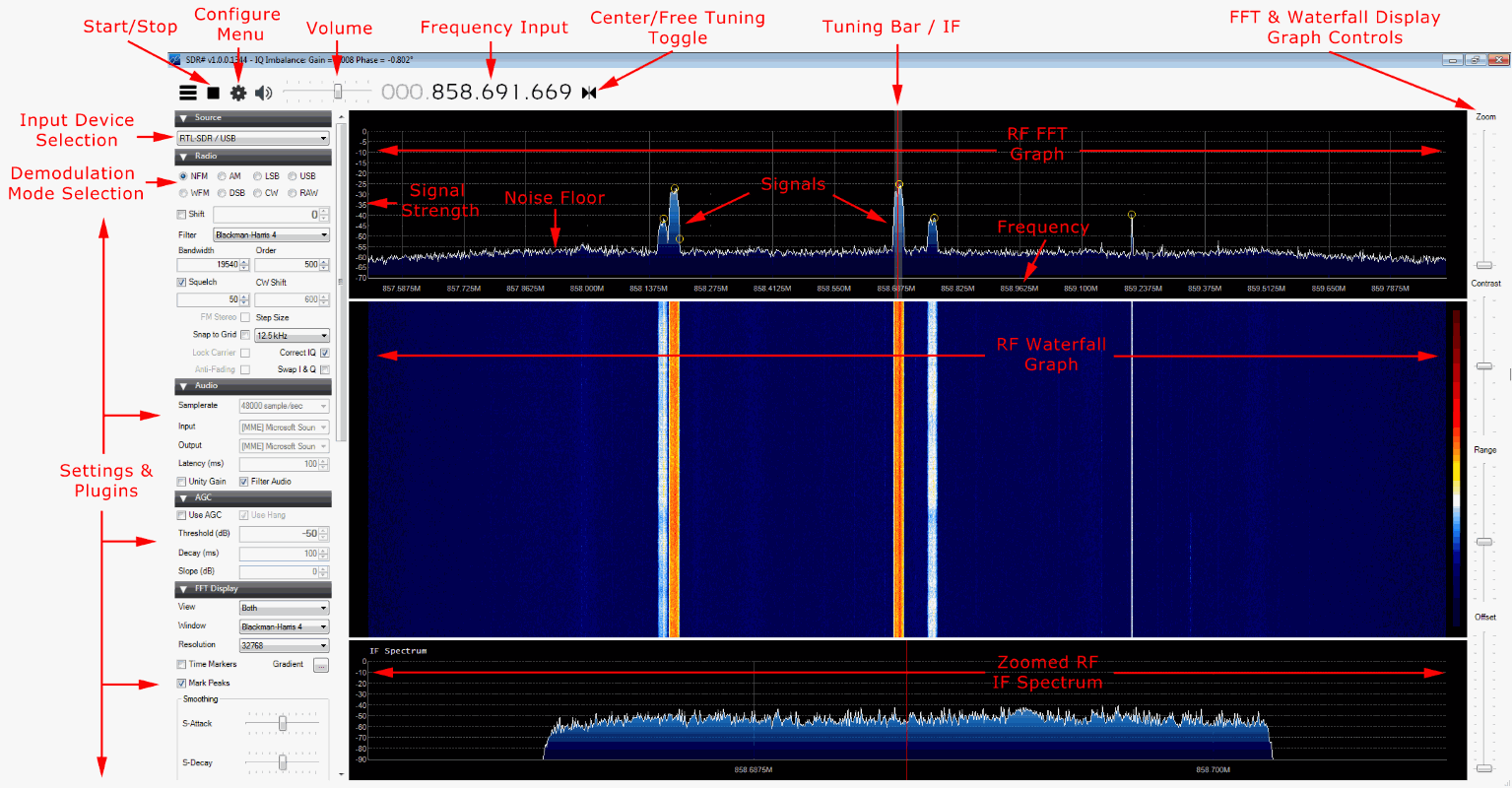
Upon opening SDR# you'll be greeted with the screen shown below. Here we have highlighted the main parts of SDR#
After opening SDR# for the first time, we suggest that you immediately remember to perform the following steps (if you don’t know what some of these steps are, continue reading further below for more information):
Increase the RF gain from zero to a higher value in the configure menu.
Reduce the range slider on the right of the SDR# window to about -70 (for RTL-SDR dongles).
Enable the “Correct IQ” setting to remove the center spike if using an R820T/R820T2, or enable “Offset Tuning” in the configure menu if using an E4000/FC0012/13.
Turn off the “Snap to grid” setting, or adjust the PPM offset accordingly.
Set the 'Mode' to the correct setting for the signal that you are listing to.
Main Settings and Windows
Note that there is a distinction in SDR# between settings that affect the software side, and settings that affect the hardware side. All hardware side settings can be found in the Configure Menu window which can be accessed with the cog icon . In here are settings to control things like the RF gain and sample rate / bandwidth of the RTL-SDR. To optimize reception, you need to adjust settings in this window.
Most of the settings found in the main windows of SDR# affect the software digital signal processing (DSP) side of things. To optimize processing of the signal you need to adjust these DSP settings.
Control/View
Explanation
Play Button / Stop Button
This button is used to start and stop the SDR.
Source
This is a drop down menu which is used to select the SDR input device being used. If you are using an RTL-SDR, select RTL-SDR/USB. Be sure to NOT select RTL-SDR/TCP unless you are using a remote server with rtl_tcp.
Configure Menu
Clicking this button opens up the configure menu. In here you can change settings like the sample rate (bandwidth) and RF gain. See further down for more information about these settings.
Frequency Input
Use the mouse to set the desired frequency you wish to listen to here. You can either click on the tops and bottoms of each individual number to increase or decrease the value, or simply hover over the number you want to change and use the mouse wheel to alter the value.
The frequency input is divided into 4 sections with each section containing 3 values (e.g. 000.000.000.000). The first section represents GHz frequency values, the second MHz, the third kHz and the last Hz. For example to tune to a radio station at 88.6 MHz we would enter 000.088.600.000 into the frequency input. To tune to 861.5475 MHz we would enter 000.861.547.500. To tune to 1.575 GHz we would enter 001.575.000.000. To tune to 500 kHz (with an upconverter and appropriate offset shift set (discussed later)) we would tune to 000.000.500.000.
Volume
Set the volume level of your output speakers or audio piping device here.
RF Spectrum / FFT Display
This part of the window shows the RF spectrum as a graph in real time visually. Active signals will appear as peaks on this graph.
RF Waterfall
This part of the window shows the RF spectrum graph spread over time with new data at the top and old data at the bottom, just like a waterfall.
Tuning Bar
The vertical red line in the RF spectrum graph shows where on the RF spectrum the RTL-SDR is currently tuned to. Within the currently active chunk of instantaneous bandwidth the tuning can be altered by simply using the mouse to click and drag the red line, or just by clicking elsewhere in the RF spectrum.
The shaded rectangular area around the red line shows the bandwidth of the tuned area (don’t confuse this with the bandwidth/sample rate that is set in the configure menu). The bandwidth should be set so that it covers the area of the signal that is tuned. The bandwidth can be adjusted by using the mouse to simply drag the edges of the shaded area in or out.
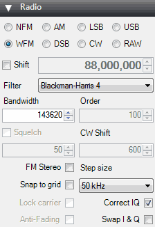
Radio Tab
Here you can choose what type of demodulation mode the signal at your currently tuned frequency should use.
Mode
Acronym Expansion
Explanation
NFM
Narrowband Frequency Modulation
Commonly used mode used by walkie talkie radios, weather radio and most VHF/UHF digital signals.
WFM
Wideband Frequency Modulation
This is the mode that broadcast FM stations use (e.g. radio music stations).
AM
Amplitude Modulation
Used by broadcast AM stations that are receivable by normal shortwave radios and also used by air band voice frequencies used by aircraft and air traffic control. Some digital signals also use AM.
LSB/USB
Lower Side Band / Upper Sideband
Used in the HF band by ham radio users to transmit voice and data efficiently with small bandwidths.
CW
Continuous Wave
Used for listening to Morse code.
DSB
Double Side Band
Similar use to AM, but requires centered tuning.
RAW
Raw IQ signal
Used for listening or recording RAW IQ data
Setting
Suggested Default
Explanation
Shift
0 (No upconverter used)
This box offsets the tuned frequency by the amount entered. This is useful if you are using an upconverter. For example if you have an upconverter with a 100 MHz oscillator, you would set the shift to be -100,000,000 (don’t forget the minus sign). Without the shift, when using an upconverter to tune to a signal at 9 MHz you would need to actually tune to 100 + 9 = 109 MHz. With the shift set, you can tune to 9 MHz as normal. If you have an upconverter with a 125 MHz oscillator you would tune to 125 + 9 = 134 MHz, or set the shift to -125,000,000.
Bandwidth
NFM/AM: 12500, WFM: 250000
This is the width of the shaded part of the tunable area. You can set it manually here, or by dragging the edges with the mouse as described under the tuning bar description.
Filter
Blackman-Harris 4
Changes the filter type used. Different filters have different shapes. The filter is used to select the highlighted signal in the RF window. Blackman-Harris is usually the best filter to choose and this setting almost never needs to be changed.
Order
500
Changes the filter order. You may notice when using low filter orders that signals outside of the tuned bandwidth can still be heard. Larger filter orders “tighten” or “sharpen” the band pass filter used within the tuned bandwidth/IF thus preventing signals outside of the tuned bandwidth from being heard. You will want to increase the filter order when there are strong signals near to your tuned area. Using higher filter orders can cause a greater load on the CPU, so slow PCs may need to reduce this value.
Squelch
OFF
Squelch is used to mute the audio when the signal strength is below the specified value. A larger value requires a stronger signal to unmute the audio. It is useful for when listening to speech as the sound of static when no one is talking will be muted.
CW Shift
600
Mainly useful for when receiving CW (Morse code) as it specifies the offset between CW transmit and receive frequencies.
FM Stereo
OFF
Will enable stereo output for broadcast radio WFM signals, but can make weak stations sound worse.
Snap to Grid / Step size
OFF or set to band spacing
In many bands frequencies are allocated at a fixed distance apart. For instance in most countries air band signals are spaced 25 kHz apart (or 8.33 kHz in some countries). Turning on snap to grid can help with tuning by causing the tuning bar to snap directly to a signal. However, to use this with a non-TCXO RTL-SDR the PPM frequency offset correction must be set correctly, otherwise the frequencies may not line up. The snap to step size can be set in the “Step Size” pull down menu.
Correct IQ
ON
Should usually be selected as ON. This setting removes the small but annoying center spike that is present with R820T/R820T2 RTL-SDR dongles.
Lock Carrier
OFF
Only active in AM or DSB mode. Allows for synchronous AM which can significantly improve reception and also automatically centers the signal on the carrier. Turn this on for better AM reception, but may increase CPU usage.
Anti-Fading
OFF
Can be used when “Lock Carrier” is activated. Takes advantage of the symmetry of AM signals which helps with weak signals when they may be fading in and out. Turn this on for better AM reception, but may increase CPU usage.
Swap I & Q
OFF
If you are using SDR# as a panadapter, some hardware radios may have the I & Q signals swapped and need this option checked.
Mark Peaks
OFF
Simply marks any peak in the RF spectrum with a circle.
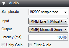
Audio Tab
This tab allows you to adjust settings related to the audio processing.
Setting
Suggested Default
Explanation
Sample Rate
48000
Sets the sample rate of your sound card. Some decoding software may require a specific sample rate to be set. Usually the default value should be fine for general listening. This is normally greyed out unless using a sound card based SDR.
Input
A Sound Card
Specifies the input sound card when using SDR# with the “Other (Sound Card)” source. Used mainly with sound card based software defined radios. In normal use with an RTL-SDR this does not need to be set.
Output
Speakers
Sets the audio output device. By default it is set to your speakers. If you are passing the audio to a decoder program here you would choose your virtual audio pipe (VAC/VB Cable) to send the audio to.
Unity Gain
OFF
Should normally be unchecked as it sets the audio gain to 0 dB.
Filter Audio
ON
Improves voice signals by filtering the audio, removing high pitched hiss and DC noise. Should normally be off if decoding digital signals, but may actually help in some cases if there is significant DC offset.
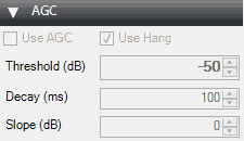
AGC (Automatic Gain Control) Tab
Note that in some modes the AGC tab will be greyed out.
Setting
Suggested Default
Explanation
Use AGC
ON
Turns on the audio automatic gain control. The AGC will attempt control the audio volume level so that loud sounds are not too loud and quiet sounds are not too quiet. The default settings work well for voice audio signals. It is especially useful to turn this on when listening to AM/USB/LSB signals as strong signals in these modes may sound distorted otherwise.
Use Hang / Threshold / Decay / Slope
-50, 100, 0
Allows you to modify the default AGC behavior, though in most cases the defaults are fine.
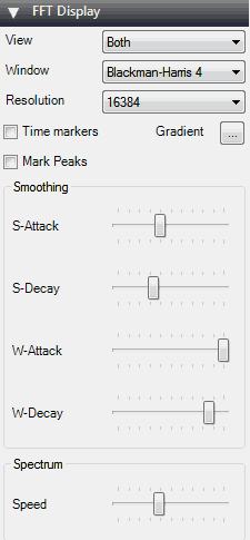
FFT Display
The FFT display settings adjust options related to the spectrum analyzer screen and the waterfall.
Setting
Suggested Default
Explanation
View
Both
Set it to view both the RF spectrum and the waterfall, or only one of them, or none at all. Removing the waterfall may be useful on older PCs with slow processing hardware.
Window
Blackman-Harris 4
Sets the type of windowing algorithm to use on the FFT, the default of Blackman-Harris 4 is the best in most cases.
Resolution
32768
Increasing the resolution will increase the quality of how the signal looks in the RF display and waterfall. Using a higher resolution may be useful when fine tuning, as high resolutions will allow you to see the peaks and structure of a signal much more clearly. Beware that high resolutions can slow your PC down and can cause trouble especially with single core machines. Generally, a value of at least 32768 should be used if your PC can handle it.
Time Markers
OFF
Adds time markers on the waterfall display, so you know at what time a particular signal was broadcasting.
Gradient
Allows you to customize the colors used in the waterfall display.
Mark Peaks
OFF
Adds a circular marker on every signal peak on the RF spectrum.
S-Attack / S-Decay
Changes the amount of smoothing and averaging done in the RF spectrum display.
W-Attack / W-Decay
Changes the amount of smoothing and averaging done in the waterfall display.
Speed
Changes how fast the RF spectrum and waterfall updates.
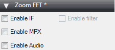
Zoom FFT
Zoom FFT is a plugin that comes by default with SDR#. It creates a zoomed in RF spectrum display of the tuned IF bandwidth at the bottom of SDR#.
Setting
Explanation
Enable IF
Opens a “zoomed in” RF spectrum graph around the area of your tuned IF bandwidth. Allows you to see the signal structure with much greater resolution.
Enable Filter
If Enable IF is checked, then you can enable a special adjustable IF filter. This filter allows you to filter the left and right side of the tuned IF bandwidth individually.
Enable MPX
Enables you to see the MPX spectrum of a broadcast FM radio station. Broadcast FM is encoded in a special baseband audio format called MPX. It contains a mono section, a pilot tone and a stereo section, as well as sometimes subcarrier sections for data like RDS and special radio services like SCA. If you were to try and view the audio baseband with the “Enable Audio” button, you wouldn’t see the MPX structure because SDR# would have processed it into normal audio, and discarded the subcarriers and other sections.
Enable Audio
Allows you to see the audio (baseband) spectrum.
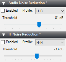
SDR# Digital Noise Reduction
It is useful to turn on digital noise reduction when listening to weak and noisy analogue voice signals. This setting will attempt to reduce the background ‘hiss’ sound. There are two DNR options available, IF and Audio. The IF uses the noise reduction algorithm on the IF signal and the Audio option does it on the output audio signal. Usually the IF digital noise reduction works best and should be tried first, though a combination of both may work best. The sliders control the strength of the algorithm applied, and the profile can be optimized for the type of audio you are listening to. The profile options are Hi-Fi, Talk, Speech, Narrow Band and custom.
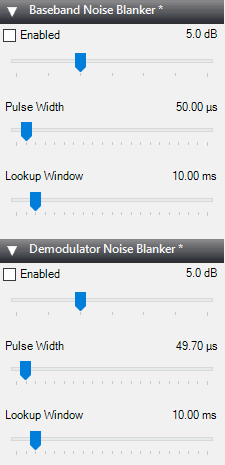
Noise Blanker
The noise blanker is an algorithm that can be turned on to help reduce impulsive and pulsing like noise from sources like spark gaps. Examples of this type of noise may come from motors, electricity lines, power over Ethernet and switching power supplies. Carefully using this option can really help when receiving a weak signal amongst pulsating noise, which is mostly common on the HF bands. The noise blanker works by simply removing any samples that have large pulses of energy in them.
In SDR# there are two different types of noise blanker. The baseband noise blanker works on the entire spectrum and will remove pulses from the FFT and waterfall, whereas the demodulator noise blanker only works within the tuned area that is currently being demodulated. Tuning the settings is mainly an exercise in trial an error. Move the sliders until the pulsating noise goes away, whilst trying to keep the signal active.
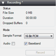
Recording Tab
The recording tab allows you to make I/Q and Audio recordings. The sample format allows you to choose the level of recording quality needed. Since the RTL-SDR is only about 8-bits, we can select the lowest 8 Bit PCM option. Using only 8-bits saves a significant amount of disk space.
An I/Q recording is a recording of the entire ~2 MHz bandwidth that you are currently tuned to. It saves the RF data within the bandwidth so you can replay it at a later time. An I/Q recording can be made by checking the “Baseband” check box. Note that I/Q recordings can use up a lot of disk space, so make sure to watch the File Size and Duration status counters. I/Q recordings can be played back in SDR# by selecting IQ File (*.wav) from the source menu. If you receive a lot of dropped buffers, then your PC or disk may simply not be fast enough to process the recording. Remember that baseband recordings use a lot of disk space.
The audio coming out of the speakers can be recorded by checking the “Audio” check box. This will record audio to a standard audio .wav file. All recorded files are stored in the same folder as the SDR# executable.
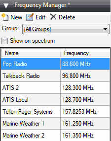
Frequency Manager Tab
The frequency manager allows you to save any frequencies of interest in a database. A new frequency can be added to the database by clicking in the New button. This will add a frequency with the current tuned frequency and settings like bandwidth. You can edit the frequencies name and put it into a group for easy management. Double clicking on a stored entry will instantly tune SDR# to that frequency, and set the stored mode and bandwidth.
If you check the “Show on spectrum” check box then your saved frequencies will be displayed in the RF spectrum.
Right hand side sliders
The sliders on the right adjust the graph display settings for the RF spectrum and waterfall.
Setting
Suggested Default
Explanation
Zoom
Zoomed out
Moving this slider will cause the RF spectrum and waterfall to zoom in on your tuned IF bandwidth area in order to see a signal closeup. However, the more you zoom in, the lower the resolution will seem. An alternative to zooming is to either reduce the sample rate, or to use the special decimation drivers. These alternative methods will preserve the visual resolution and allow you to see the signal structure much more clearly.
Contrast
Adjusts the contrast of the waterfall. Adjust it so that signals clearly stand out from the background noise.
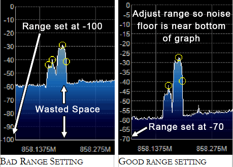
Range
-70
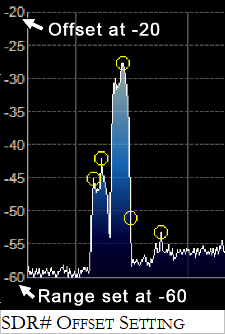
Modifies the dB level range shown on the left (vertical) axis of the RF spectrum window. You should adjust this so that the noise floor sits near the bottom of the RF spectrum window. This will allow signals to be more visible in the FFT RF spectrum and waterfall displays. As the RTL-SDR has a dynamic range of approximately 50 dB (plus a little more after oversampling/decimation), you will not need a range much higher than 0 to -70 dB. This setting will also affect the contrast in the waterfall and may help make weak signals easier to spot.
Offset
0
Adds an offset to the dB level range in the RF spectrum window. The offset is added to the top value on the dB level range in the RF spectrum. Usually there is no need to adjust this, but if you want to get really good contrast on weak signals, adjust this along with the range so that the signal height is the same height as the vertical axis. This setting will also affect the contrast in the waterfall and may help make weak signals easier to spot.
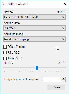
Configure Window / RTL-SDR Controller
The SDR# configure window can be accessed by clicking on the cog icon at the top of the SDR# window. The settings in this window affect the actual RF performance of the RTL-SDR, and should be set correctly to optimize the signal to noise ratio (SNR). The configure window has several options which are described below.
Remember that some options may be greyed out until you press stop in SDR#.
Setting
Suggested Default
Explanation
Device
Your RTL-SDR
If you have multiple RTL-SDR dongles plugged in, the device drop down menu allows you to choose between them.
Sample Rate
2.048 or 2.4 MSPS
Lets you choose the size of the instantaneous bandwidth the RTL-SDR should display. Generally settings of up to 2.8 MSPS work well on most PCs, but if you have a slow PC you may want to reduce this. We recommend a default rate of 2.048 or 2.4 MSPS.
Sampling Mode
Quadrature Sampling
Use Quadrature sampling for normal operation. The direct sampling selections should be used when using an RTL-SDR that supports it.
Offset Tuning
R820T/2 : OFF
E4000/FC0012/13 : ON
Only useful for the E4000/FC0012/13 tuners. Selecting this will get rid of the large spike in the center of the spectrum that is present with the E4000/FC0012/13 zero IF tuners.
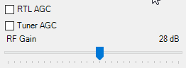
RTL AGC
OFF
Enables automatic gain control on the RTL2832U chip. This is normally not useful as selecting this usually degrades reception.
Tuner AGC
OFF
Enables the automatic gain control system on the tuner chip. Can be useful for general browsing, but it is almost always better to set the gain manually.
RF Gain
Adjust for best signal to noise ratio
This slider can be used to set the tuner RF gain manually. Will not be active if Tuner AGC is checked.
Frequency correction (ppm)
TCXO Dongle: 0
Standard Dongle: Adjust for freq. accuracy.
Allows you to correct the frequency offset that RTL-SDRs have from having low quality crystal oscillators.
Setting the RF Gain
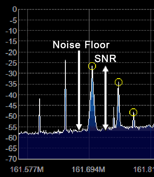
There are three RF gain settings that can be found by clicking on the Configure button. RTL AGC turns on the RTL2832U chips internal automatic gain control (AGC) algorithm. Tuner AGC enables the RTL-SDR tuners AGC. The AGC’s attempt to automatically optimize the SNR of the signals. Finally, the gain slider can be used to manually set the gain.
The AGCs used in the RTL-SDR are designed to be used with wideband DVB-T signals, and do not work very well with narrowband signals. We recommend using manual gain control at all times to optimize the gain of a signal, however for casual browsing turning on Tuner AGC may suffice. RTL AGC is almost never used as it tends to just introduce a lot of unwanted noise.
The goal when setting the RF gain manually is to try and get the signal to noise ratio (SNR) as high as possible. This means that the maximum signal strength should be high, but the noise floor should also be as low as possible.
When increasing the gain, there will come a point at which the noise floor begins to rise faster than the signal strength rises. This is the point at which you should stop increasing the gain.
You can calculate the signal to noise ratio by subtracting the peak signal height from the height of the noise floor.
What Overload Looks Like
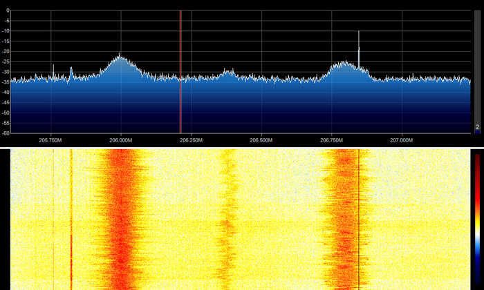
In SDR's (and all radio's for that matter), overload is when a signal that is too strong enters the radio and causes “saturation”. An analogy might be trying to listen to your friend talking to you at a loud concert. The music from the speakers is so loud that you can't hear what they are saying. The same thing can happen in radios. For example if the SDR cannot cope with a strong signal and starts overloading, weaker signals will no longer be able to be heard. This can happen even if there is a strong signal hundreds of MHz away from your target signal, though the closer in frequency it is the more problematic it will be. The biggest causes of overload are broadcast FM signals, pagers, TV broadcasts, DAB radio and GSM signals.
The first solution to overload is to simply turn the gain down. But turning the gain down can also make your desired signal weaker, so ideally you'd use a filter to remove those unwanted strong signals, or buy a more expensive 12-bit or higher SDR which can handle strong signals much better. In this section we'll show you what overload looks like on SDR#, so you'll know when to recognize if there is a problem.
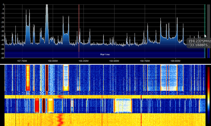
Overload can manifest itself as images of the strong signal at frequencies where they're not meant to be. For example in the image below there are broadcast FM stations at 206 MHz, and they definitely should not be there. Simply turning down the gain causes them to disappear.
BCFM Images
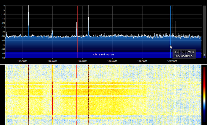
It can also manifest as a rise in the noise floor. For example in the image below a strong pager signal is causing the noise floor to rise whenever it transmits, and then fall again when it stops.
Pager Causing Noise Floor Rises
If you are tuned only a few MHz away from a very strong signal it can cause all sorts of weird images to show up . For example in this image below, whenever the pager transmits it causes strange signal spikes all over this part of the spectrum.
Of course overload can also cause the noise floor to rise so high that the signal is no longer visible at all.
Pager Overload
SDR Sharp Plugins
There are many plugins available for SDR# that extend its functionality. We recommend visiting rtl-sdr.com/sdrsharp-plugins for a list and brief overview of these plugins.
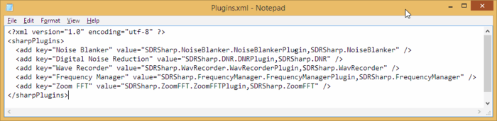
To install plugins you will most often need to copy a .dll file to the SDR# directory and add a 'magic line' text entry to the Plugins.xml text file which can be found in the SDR# directory. You will need to open this file in Notepad or another text editor to read it. The readme file that usually comes in the plugin zip file will usually tell you what the 'magic line' is. The line should be added between the <sharpPlugins> </sharpPlugins> tags.
Note that some older plugin readme files may still instruct you to add the line to the SDRSharp.exe.config file. This was used in older SDR# versions and is now incorrect. The line should be added to the plugins.xml file now.
If you enjoyed this tutorial you may like our eBook available on Amazon.
SDR# plugin developer Eddie Mac has again released a new plugin for SDR# called "SDR# Plugin Manager". This plugin is designed to make it easy to install, remove and re-order other SDR# plugins. Also included is a repository browser. This is a repository of many known SDR# plugin links which can be used to download and install a plugin with a simple click of a button.
If you are interested in programming your own plugins, Eddie also offers the following advice which he posted in our forum:
A good place to get started programming plugins is to download the express version of .NET (free for personal use) and install at least the C# pack. Then go to the Airspy website and download Youssef's zipped examples on coding plugins. While they are not documented you can use them as an example of the steps involved.
If you know a bit of c++ that is great it should be a good spring board to learn C#. In fact, you can even program simple plugins (like my tuner knob) in Visual Basic. Both C# and VB.NET compile to Common Language Run time anyway so to SDR# it's not much difference. The only caveat is that if you want to create any plugins to do processing on signals of any sort you MUST use C# as it supports the data types SDR# uses and VB does not. As well, VB does not allow unsafe code which C# can be instructed to allow.
Another great resource for learning to program plugins for SDR# is GitHUb and another great place is Andrej Mohar's website where he actually has a tutorial and an good explanation of the plugin coding process. You can find it here http://www.andrej-mohar.com/plugin-basics-for-sdr
If you would like an example of a "stencil" as you call it - a template, I would be happy to share a template in both VB and C# for you to use to start to learn. However, I would suggest begginning with C# from the start.
The basics of it is that the "plugin" is actually in interface that is called while SDR# loads. The "Plugins.xml" file tells SDR# what your dll is called and what the name of the plugin is. Once it has initialized your plugin, SDR# sharp asks the plugin for a "panel" control which contains the controls for your plugin. In also returns to you a "control" object interface that allows you to receive notifications of program value changes or to set program values. There are more complex things you can do but the basics are simple.
Over on Twitter and his github.io page, Pieter Noordhuis (@pnoordhuis) has shared details about his low cost RTL-SDR based GOES satellite receiving setup. GOES 15/16/17 are geosynchronous weather satellites that beam back high resolution weather images and data. In particular they send beautiful high resolution 'full disk' images which show one side of the entire earth. As the satellites are in geosynchronous orbit, they are quite a bit further away from the earth. So compared to the more easily receivable low earth orbit satellites such as the NOAA APT and Meteor M2 LRPT satellites, a dish antenna, good LNA and possibly a filter is required to receive them. However fortunately, as they are in a geosynchronous orbit, the satellite is in the same position in the sky all the time, so no tracking hardware is required.
In the past we've seen people receive these images with higher end SDRs like the Airspy and SDRplay. However, Pieter has shown that it is possible to receive these images on a budget. He uses an RTL-SDR, a 1.9 GHz grid dish antenna from L-Com, a Raspberry Pi 2, the NooElec 'SAWBird' LNA, and an additional SPF5189Z based LNA. The SAWBird is a yet to be released product from NooElec. It is similar to their 1.5 GHz Inmarsat LNA, but with a different SAW filter designed for 1.7 GHz GOES satellites. The total cost of all required parts should be less than US $200 (excluding any shipping costs).
Pieter also notes that he uses the stock 1.9 GHz feed on the L-com antenna, and that it appears to work fine for the 1.7 GHz GOES satellite frequency. With this dish he is able to receive all three GOES satellites at his location with the lowest being at 25 degrees elevation. If the elevation is lower at your location he mentions that a larger dish may be required. It may be possible to extend the 1.9 GHz L-Band dish for better reception with panels from a second cheaper 2.4 GHz grid dish, and this is what @scott23192 did in his setup.
For software Pieter uses the open source goestools software that Pieter himself developed. The software is capable of running on the Raspberry Pi 2 and demodulating and decoding the signal, and then fully assembling the decoded signal into files and images.
Over on YouTube the web show Hacker Warehouse have created a video explaining wireless pagers and how RTL-SDRs can be used to sniff them. In the video host Troy Brown starts by explaining what pagers are and how they work, and then he shows how to decode them with SDR# and PDW. We have a tutorial on this project available here too.
Later in the video he shows some examples of pager messages that he's received. He shows censored messages such as hospital patient data being transmitted in plain text, sports scores, a memo from a .gov address claiming allegations of abuse from a client, office gossip about a hookup, a message about a drunk man with a knife, a message from a Windows server with IP address and URL, a message from a computer database, and messages from banks.
In the past we've also seen an art installation in New York which used SDR to highlight the blatant breach of privacy that these pager messages can contain.
In the past the Outernet project operated on L-band frequencies, and for the service they manufactured a number of active L-band active ceramic patch antennas for use with RTL-SDR dongles. Outernet has since moved on to faster Ku-band delivery, and hence their old L-band antennas can no longer be used for their service. There are a few of these patch antennas left over in Outernet's stock and they are currently selling them on eBay for US $29 + shipping.
Although no longer useful for Outernet, these antennas are still very useful for receiving other L-band services such as STD-C SafetyNET and AERO. SafetyNET is a text broadcast intended for sailors at sea, but contains many interesting and potentially useful messages for others too. Often they transmit data like military sea live firing warnings, reports of marine pirate activity, search and rescue reports, scientific vessel reports as well as weather reports. AERO is the satellite version of ACARS, and is used by aircraft to communicate with text messages to and from ground stations. L-Band AERO signals only contain information from the ground station up to the aircraft. For air to ground you'll need a C-band receiver set up. AERO is the satellite communications protocol that was so heavily centered on during the MH370 flight disappearance investigation.
In the past we've reviewed the Outernet L-band ceramic patch and found it to work very well. Certainly STD-C and AERO signals are easy to receive with the antenna if you point it at the satellite. The antenna requires bias tee power and can easily be used in combination with the bias tee on our RTL-SDR V3 dongles. The onboard filter helps reduce problems from interfering signals, but restricts reception to 1525 - 1559 MHz, so Iridium signals cannot be received with this antenna.
The L-Band Active and Filtered Ceramic Patch Antenna.
 Thank you to RTL-SDR.com reader 'JJ' for writing in with a submission for his Lego Pi Radio. JJ's Lego Pi Radio consists of a Raspberry Pi and RTL-SDR and is designed to be an FM Radio, MP3 and internet radio player all in one, with a cute enclosure made out of Lego bricks. The radio is controlled by an external numpad which allows for a number of presets to be chosen from.


 . In here are settings to control things like the RF gain and sample rate / bandwidth of the RTL-SDR. To optimize reception, you need to adjust settings in this window.