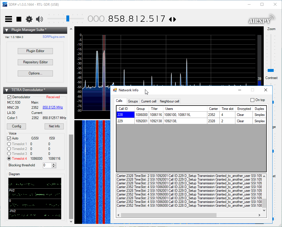
In the new version the 'Net Info' button is now functioning and it is possible to see the current calls, groups, and meta information on the current cell and neighbour cell. It also appears that it has been updated to allow for multiple SDR# TETRA decoder instances to be opened simultaneously now for wider band monitoring.
Thank you to Michael (dg0opk) who wrote in and wanted to share details of his full SDR monitoring system for weak signal HF modes. His setup consists of nine ARM mini PCs (such as Banana Pi's, Raspberry Pi's, and Odroid's), several SDRs including multiple RTL-SDR's, an Airspy Mini, FunCube Dongle and SDR-IQ, as well as some filters and a wideband amp. For software he uses Linrad or GQRX as the receiver, and WSJTx or JTDX as the decoding software, all running on Linux.
Michael also notes that his Bananapi FT8, JT65 and JT9 SDR monitor has been up and stably running continuously for half a year now. Bananapi's are lower cost alternatives to the well known Raspberry Pi single board computers, so it's good to note that a permanent weak signal monitoring system can be set up on a very low budget. Presumably even cheaper Orange Pi's would also work well.
With his setup he is able to continuously monitor FT8, JT65 and JT9 on multiple bands simultaneously without needing to tie up more expensive ham radios. His results can be seen on PSKReporter. A video of his RTL-SDR Raspberry Pi 3 decoding FT8, JT65 and JT9 can be found here.
Over on YouTube Jack Riley has created a video that documents his system which uses an RTL-SDR to receive POCSAG pager messages and forward messages sent to specific pager addresses to an email address. He uses his RTL-SDR on a Raspberry Pi, together with rtl_fm and multimon-ng to receive and decode the pager messages.
Then using a custom program that is available on his website he filters messages for a particular 'capcode' which indicates the address of a particular pager. When a pager message to the specified capcode address is received, the program turns the message into an email which is instantly sent out.
This is a nice way to forward pager messages on to a more modern device such as a smart phone.
Creating a Pager using a Raspberry Pi and RTL-SDR to send alerts via Email.
A linear transponder is essentially a repeater that works on a range of frequencies instead of a fixed frequency. For example, a normal repeater may receive at 145 MHz, and repeat the signal at 435 MHz. However, a linear transponder would receive a wider bandwidth, and add a set frequency offset to the received signal. For example a signal received by a linear transponder that receives from 145 - 145.5 MHz, may receive a signal at 145.2 MHz and it would translate that up to 435.2 MHz. Another signal received at 145.4 MHz would translate up to 435.4 MHz. Hence the received frequency linearly translates to the transmitted frequency.
AERO is essentially the satellite based version of aircraft ACARS. AERO's L-band signals contains short ground to air messages with things like weather reports and flight plans. The C-band signals are the air to ground portion of AERO and more difficult to receive as they require an LNB and large dish. However they are much more interesting as they contain flight position data, like ADS-B.
Over on YouTube Tomasz Haddad has uploaded a video of C-band AERO being received from the Inmarsat 3 F2 (Atlantic Ocean Region – East (AOR-E) 15W satellite. He uses a 1.80m motorized satellite dish with Kaonsat KS-N201G C-band LNB, a Prof 7301 PCI satellite card (to power the LNB) and an RTL-SDR V3. The C-band LNB translates the high C-band frequencies down to L-band which is receivable with an RTL-SDR. He notes that the LNB drifts quite a lot as it is not frequency stabilized.
With the signals received by his setup he's able to use the JAERO decoding software together with Virtual Radar Server to plot aircraft positional data using Virtual Radar Server. The plotted aircraft are mostly all in the middle of the ocean or in remote areas, which is where C-band AERO is normally used due to the lack of ground ADS-B stations.
Inmarsat 3 F2 15W C Band AERO Reception Using Jaero And Virtual Radar
During the SANS Pen Test HackFest which was held back in 2017, speaker Katie Knowles who is a security consultant at MWR Infosecurity did a very informative talk on how an RTL-SDR can be used to investigate RF signals. The video has recently been uploaded to YouTube and is shown below. In the talk she goes over how to reverse engineer and understand simple RF protocols, like those used by common RF remote controls found in the home. She then goes on to talk about the basics of software like GNU Radio and rtl_433. The talk blurb reads:
Cranes, trains, theme park rides, sirens, and …ceiling fans? Modern RF protocols have made secure wireless communications easier to implement, but there’s still a horde of simpler RF control systems in the wireless world around us.
Lucky for us, the onset of affordable Software Defined Radios (SDRs) means that exploring these devices is easier than ever! In this talk, Katie examines capturing and understanding basic RF control signals from a common household controller with the affordable RTL-SDR so you can start your own investigations.
With a little knowledge of these protocols we can better explain what makes them risky to the environments we assess, practice thinking in the offensive mindset, and have some fun examining the signals around us.
Signal Safari: Investigating RF Controls with RTL-SDR – SANS Pen Test HackFest 2017
Back in April we posted about QuestaSDR, which had just released the Android version of its SDR software. Recently QuestaSDR programmer 'hOne' wrote in and noted that a new update has enabled remote streaming in QuestaSDR.
To get set up, just run the Windows version of QuestaSDR on a PC, and open the "SDR Server" app. Once the server is running, you can connect to it via the Android version of QuestaSDR over a network connection. The server supports the RTL-SDR, Airspy and any ExtIO compatible device such as SDRplay units. As far as we're aware, this is the only Android app that currently supports streaming from non rtl_tcp compatible units such as the Airspy and SDRplay.
The Tzumi MagicTV is a device that allows users in the USA to watch TV on an Android phone via free over the air digital ATSC signals. It receives and decodes TV on the device, then streams decoded TV to an Android phone via a WiFi connection.
Over on Reddit user meowTheKat has alerted everyone to the fact that 'Tzumi MagicTV' devices contain not only an R828D RTL-SDR inside them, but also an AR9331 OpenWRT board and a 3000 mAh battery pack. This means that the device could potentially be used as a portable RTL-SDR server over a WiFi connection without any additional required hardware. And right now is a particularly good time for this discovery to come out, as the device is reportedly selling at a clearance sale price of only $13 at Walmarts across the USA.
OpenWRT is custom open source firmware that is intended to be installed on compatible internet routers. It extends the functionality and stability of many routers. Since OpenWRT is based on Linux, it is possible to use the RTL-SDR on routers running OpenWRT and we have several previous posts about people doing this.
Currently meowTheKat reports that the MagicTV is indeed running OpenWRT, and that SSH is available. The SSH password is unknown but a colleague of his is currently working on cracking the password. Once cracked it should become possible to install RTL-SDR software on to it. However, there is no word yet on if the front end has additional filtering specifically for TV signals or not. If there is additional filtering those circuits would need to be removed to restore wideband tuning to the RTL-SDR.
Update: From discussion on the Reddit thread it appears that the tuner chip used is not an R828D as first thought, but instead a MXL603/608. This tuner is currently not supported in the RTL-SDR code, but support could probably be added by a developer.
The "Tzumi MagicTv" contains an RTL-SDR, OpenWRT Board and Battery Pack.
Cubesats are small shoebox sized satellites that are usually designed by universities or amateur radio organizations for basic space experiments or amateur radio communications. Typically they have an orbit lifespan of only 3-6 months.
Cubesats typically transmit signals at around 435 MHz, and they are powerful enough to be received with a simple home made antenna and an RTL-SDR. To help with this Thomas N1SPY has created a YouTube video where he shows exactly how to construct a cheap eggbeater antenna made out of a few pieces of copper wire and an SO-239 UHF connector. Later in the video he demonstrates some Cubesats being received with his antenna, an RTL-SDR and the SDR-Console V3 software.
Over on GitHub dbdexter-dev has released a new lightweight and open source Meteor M2 demodulator. Meteor M2 is a Russian weather satellite that transmits images down in the digital LRPT format. This provide much higher resolution images compared to the NOAA APT signals. With an RTL-SDR, appropriate satellite antenna and decoding software it is possible to receive these images.
This new lightweight demodulator may be especially useful for single board PCs like the Raspberry Pi. Previously, on Linux GNU Radio based demodulators have been used, and GNU Radio isn't exactly a light weight piece of software. To use the software you first need to record an IQ file of the Meteor M2 LRPT signal, downsample the IQ file to 140 kHz (if required), then pass it into the demodulator. This will spit out an 8-bit soft-QPSK file which can be used with LRPTofflinedecoder (now known as M2_LRPT_Decoder) on Windows or meteor_decoder on Linux to generate an image.
An Example LRPT Image Received with an RTL-SDR from Meteor-2 M2.
SimpliSafe is an American DIY home security system company that claims over 2 million customers. Their system relies on 433/315 MHz ISM band wireless radio communications between its various sensors, control panels and remote controls. Back in 2016 we already posted about research from Dr. Andrew Zonenberg and Micheal Ossmann who showed that the SimpliSafe wireless communications are unencrypted, and can easily be intercepted, decoded, and spoofed. SimpliSafe responded to those concerns by downplaying them and mentioning that sophisticated hardware was required.
Adam began with some initial manual RF analysis with an RTL-SDR, and then later worked with rtl_433 dev Christian Zuckschwerd to add PiWM demodulation capability, which is the modulation used by SimpliSafe systems. Now Adam is able to easily decode the serial number, pin codes, and status codes transmitted by SimpliSafe sensors and key pads in real time with just an RTL-SDR.
This is very concerning as not only could a burglar easily learn the alarm disarm pincode, but they could also profile your behavior to find an optimal time to break in. For example if you arm your alarm before bed, and disarm in the morning your sleep schedule is being broadcast. It is also possible to determine if a particular door or window has been left open. With a tuned Yagi antenna Adam was able to receive signals from 200+ feet (60m) in free space, and 115 feet (35m) through walls.
In addition to the lack of encryption, Adam also discovered that the SimpliSafe system was susceptible to jamming attacks, and that the tamper detection system can be easily compromised. Adam has disclosed all concerns and findings to SimpliSafe who are aware of the problems. They assure him that next generation systems will not suffer from these flaws. But unfortunately for current generation owners, the hardware will need to be eventually replaced as there is no over the air update capability.
Inspired by a low flying aircraft that kept waking his cat in the morning, Simon Aubury decided to use an RTL-SDR and ADS-B tracking software dump1090 to determine which plane was the culprit. This is all now standard stuff, however, Simon's software implementation and management of the received ADS-B data is quite unique, as he uses Apache Kafka, KSQL and Kibana as his tools for processing and visualizing the ADS-B data.
Apache Kafka is a 'distributed streaming platform', and KSQL enables real time processing of the data from Kafka. Kibana is a data visualization tool. Essentially these technologies are just ways to manage, process and digest in a human readable way large amounts of real time data coming into a database.
So with some clever database coding Simon was able to create a constantly updating dashboard in Kibana that plots aircraft positional heat maps, displays data such as spotted airlines and destination frequencies in a text cloud, and displays aircraft height data in a line graph. Finally using a database lookup and his gathered data Simon was able to determine that an A380 aircraft flying over his house was waking his cat in the morning.
Over on YouTube OM0ET has shown how he uses his RTL-SDR for measuring crystals. While working on his home made HF 6-band SSB transceiver, OM0ET needed a way to measure the frequency of some 8 MHz crystals that he needed for his IF filter.
To perform the measurement he simply inserts the crystal into a homemade oscillator circuit, and measures the output with an RTL-SDR V3 operating in direct sampling mode. With the measurements he's able to figure out if the crystal is actually working in the first place, and secondly determine an accurate frequency measurement.
RTL-SDR USB receiver - cheap tool for matching crystals
As Outernet is currently having a sale and selling their their moRFeus product at only US $99 (see next post for details - or simply use coupon code "rtlsdrblog" on their checkout - valid until Saturday 09 May 18), we thought that we'd show an interesting use for the moRFeus when combined with an RTL-SDR.
Outernet's moRFeus is a signal generator and frequency mixer that can be controlled either by it's built in LCD screen, or via software on a Windows or Linux PC. It can generate a clean low phase noise tone anywhere between 85 to 5400 MHz. Because it can be computer controlled it is possible to use moRFeus as a tracking generator for characterizing filters and measuring antenna SWR. A tracking generator is just a signal generator that can be set to output at the same frequency that the measurement receiver is tuned to.
In the past we've posted a tutorial showing how to use a wideband noise source for measuring filters and antenna SWR. However, if available, a tracking generator is usually preferred over a noise source. A wideband noise source outputs high power at all frequencies, and so can easily overload an RTL-SDR causing reduced dynamic range and accuracy in measurements. This is especially the case when measuring bandstop filters as they pass all frequencies, apart from a small blocking band. Since so much noise gets through to the dongle, dynamic range is reduced.
This post shows how to use the moRFeus as a tracking generator together with an RTL-SDR for making RF measurements. This could be called a scalar network analyzer. The set up uses GQRX and a Python script, but in the future it is possible that someone may develop a standalone app.
Since the output of the moRFeus is quite strong, an attenuator is required to keep signal levels low enough to not overload the RTL-SDR.
The cheapest RF bridge we've found is available on eBay for about $7. With an RF Bridge you'll need a 50 Ohm dummy load as well to connect to the 'REF' port. Directional couplers seem to work more accurately however, and second hand minicircuits ones can often be found on eBay. A $2 TV 'tap' is also a directional coupler, and may also work, although we have not tested this.
Software Setup
In this tutorial we're using the method first described by 'LamaBleu' in his post to the Outernet forums. The method uses Linux and involves reading power levels from the RTL-SDR by using GQRX and it's remote telnet connection capabilities. The telnet command "F freq" can be used to change frequency in GQRX, and the command "l" can be used to read out the current power level in dbFS.
To control moRFeus we use Outernet's official "morfeus_tool", which is a command line based tool.
A basic Python script was written to set the frequency in moRFeus and GQRX at the same time. After a 500 ms settling time the power level is measured and recorded in a CSV file, then the script iterates to the next frequency. We iterate at 1 MHz intervals.
If you have a moRFeus and want to try this project out, copy and paste the script from pastebin, and name the file morfeus_scalar.py. Place the morfeus_scalar.py file and the morfeus_tool_linux_x32 tool into the home folder.
To get the software started:
Open GQRX and connect the dongle and required RF components for the test (shown below).
Set the RTL-SDR gain to zero or just low enough so that the signal doesn't cause overload (moRFeus signal levels are fairly high).
In the GQRX GUI ensure that the "Remote control via TCP" button is pressed in. (Looks like two computer screens).
Edit the Python script and choose the frequency range that you'd like to scan by setting variable FREQ_MIN and FREQ_MAX.
In a terminal run "sudo python morfeus_scalar.py".
When the script completes you'll have a file "out.txt" which is a CSV file of frequency and signal power levels.
Characterizing Filters
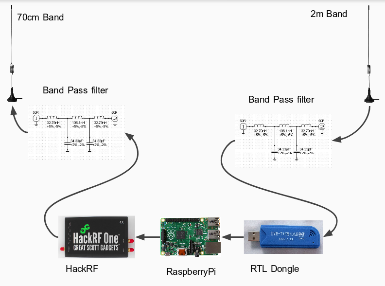
To characterize a filter (find the response of a filter) simply connect the system like so:
moRFeus Filter Test
But first connect just the moRFeus, attenuator and RTL-SDR together.
In GQRX increase the gain until just a few dB before the RTL-SDR overloads and starts showing signal images. This will maximize the available dynamic range.
Run an initial calibration scan with morfeus_scalar.py. Save the results in out.txt into a spreadsheet.
Connect the filter in the RF chain, and then run a second scan with morfeus_scalar.py. Save the results into another column in the spreadsheet.
Subtract the calibration scan results from the filtered results. Plot the resulting values using the spreadsheet software. This will show the response of the filter.
VSWR is a measurement that can be performed on antennas to determine how well matched an antenna is to (normally) 50 Ohms. Lower VSWR values are better, with a VSWR of one being the best. To measure VSWR connect the system up like in the following photo:
Measuring VSWR
First run a scan with the antenna disconnected and record the out.txt results into a spread sheet.
After the first scan completes, run the scan again with the antenna connected, and save the out.txt results to the spreadsheet.
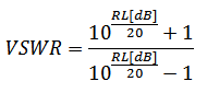
Subtract the antenna disconnected power levels from the antenna connected power levels to determine the return loss.
Here we compare the results measured by a commercial VNA (miniVNA Tiny), versus an RTL-SDR noise source measurement system, versus one using the moRFeus as a tracking generator.
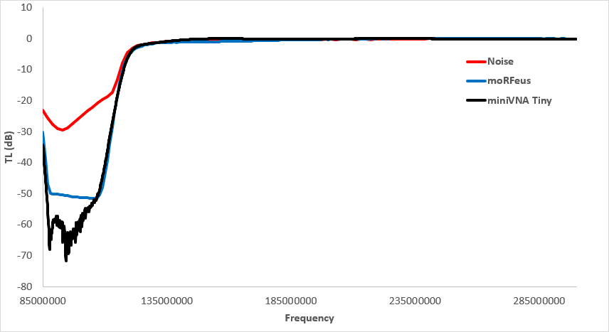
BCFM Bandstop
When measuring a bandstop filter like our RTL-SDR Blog BCFM Bandstop filter the noise source really struggles to produce an accurate result since the majority of noise over the spectrum gets through, thus overloading the dongle. It is only possible to get the rough shape of the filter.
The moRFeus tracking generator can determine the attenuation up to the maximum dynamic range of the RTL-SDR, which is about 50 dB. The VNA gets the true attenuation which is over 60 dB.
BCFM Bandstop
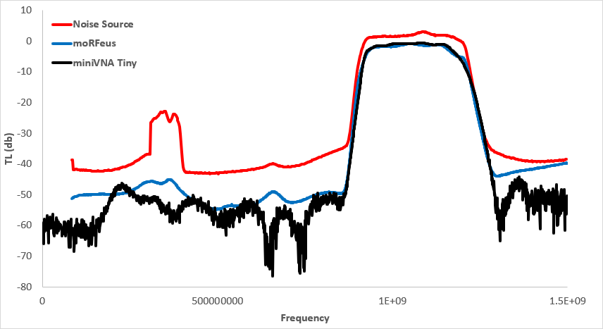
1090 MHz Band Pass Filter
Here we measure the FlightAware 1090 MHz ADS-B filter. The noise source isn't quite able to utilize the full dynamic range of the dongle, but it's better than with the band stop filter. There is also a odd glitch that occurs at around 300-400 MHz which seems to be something related to overload of the dongle.
Again moRFeus as a tracking generator gets close, but not quite down to the 60dB+ attenuation that this filter provides.
ADS-B Filter
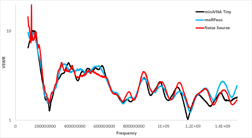
Antenna VSWR
Here we measured the VSWR of a dipole with 30 cm elements. In theory the resonant point should be around 238 MHz.
Both methods quite clearly show the resonant point of the antenna quite accurately, and are very close to the VNA's measurement. But the moRfeus tracking generator method does appear to follow the VNA's results slightly closer. The noise source method also has a bit of trouble when it comes to accurately measuring larger VSWR values, since the return loss is closer to zero, requiring more measurement accuracy.
One thing to consider is that a scan from 85 - 1500 MHz with the moRFeus and with a 500 ms settling time takes about 15 minutes to complete. Running the scan faster gives gibberish results as it seems that the measurement can't settle fast enough. A standard rtl_power scan with 2 MHz bandwidth and noise source only takes about 30 seconds, and the commercial VNA is done in 10 seconds.
We've shown that the moRFeus can be used as a low cost tracking generator together with an RTL-SDR for characterizing filters, and for measuring the VSWR of antennas. Compared to the method of using a noise source, using the moRFeus as a tracking generators gives better results that are closer to that of a commercial VNA.
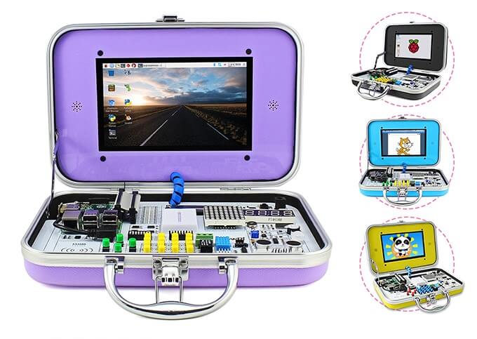
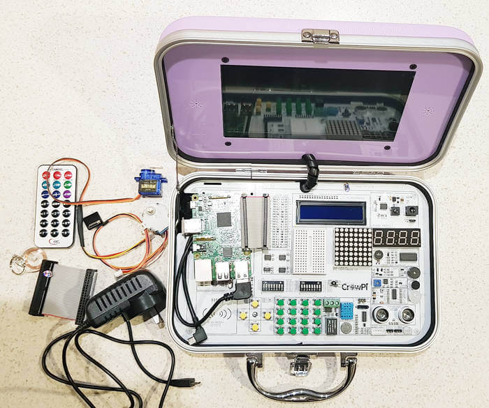
CrowPi is a Raspberry Pi all-in-one experimenters kit that is currently crowd funding on Kickstarter. The idea behind CrowPi is to combine a touchscreen, various sensors, actuators and interfaces into a clutter free kit mounted on a PCB in an easy to carry hard shell case. It's mostly intended to be used in STEM learning environments, however it could also be used for rapid prototyping of Raspberry Pi based ideas, or simply as a portable computer.
The CrowPi
The kit has 4 days left on Kickstarter and has already met its minimum goal. Pledging $1,169 HKD (~USD $150) gets you the basic kit which does not include a Raspberry Pi. Higher pledge levels (up to US$250) get you models that include a Raspberry Pi as well as extras such as a 5V power supplies, earphones, heatsinks, keyboards, game controllers etc. Shipping of the units is expected to commence in July.
Elecrow, the Shenzhen based company behind CrowPi kindly sent us a free kit for an honest review. While not directly related to RTL-SDR or RF, we thought that there might be several applications that might make the CrowPi kit useful for prototyping some simple low cost RF based ideas. For example:
Prototyping IoT based modules that use the RTL-SDR as a receiver. For example receiving a 433 MHz ISM signal and writing received information to the LCD/LED array or activating the relay.
Similarly, using FL2K-SDR or RPiTX to transmit a signal when a sensor is activated, or to transmit telemetry from that sensor (e.g. distance data from the ultrasonic sensor, humidity levels from the DH11 sensor, or light levels from the light sensor)
To get an idea of what's packed into the CrowPi, the kit includes the following modules:
Everything that came with our CrowPi Demo Kit (Except the Raspberry Pi)
1920 x 1080 Capable HDMI 7" Touch Screen
LCD Module
8x8 Matrix LED
Breadboard
4 character 7-seg LED
Vibration motor
Light Sensor
Buzzer
Sound Sensor
Motion Sensor
Ultrasonic Sensor
Servo Interface
Step Motor Interface
UART
Tilt Sensor
IR Sensor
Touch Sensor
DH11 Humidity Sensor
Relay
Matrix of buttons
RFID Module
With our kit we also received:
2x GPIO Flex Cables
1x Stepper Motor
1x Servo
1x Charger
1x IR diode
1x NFC Tag
1x Mini HDMI for the Raspberry Pi Zero
1x IR Remote control
Setup, Initial Testing and Thoughts
Setup: Setup was simple and consisted of downloading their customized Raspberry Pi image onto an SD card, connecting the Raspberry Pi to the HDMI, USB and GPIO pins, and then powering it up using the power jack on the CrowPi Board. A user manual is available for download.
Initial Testing: CrowPi provide a set of lessons that show how to use each of the modules on the board. All modules also have Python code examples that are ready to run as soon as you boot up. Immediately after booting up we were able to run their demo code which allowed us to test all the various sensors, print text to the LCD module, activate the 7-seg display, and actuate a servo and stepper motor.
The tutorials are easy to understand and provide a good basic rundown of the sensors. You will need to have some basic Python skills to understand the Python code however.
Thoughts: The CrowPi is built sturdy, and is definitely easy to use. The touch screen is bright and clear. It is capable of running in 1080P mode, but is a bit too small and hard on the eyes to use at this resolution. We kept the screen in 720P mode. In order to use the Raspberry Pi, you'll need to plug in a USB keyboard and mouse which is not included in the basic kit. A wireless keyboard/mouse combo is ideal. There appear to be speaker holes next to the monitor, but it seems that our demo model is the basic model which does not include built in speakers. The kit is impressive looking and appears to be priced reasonably for what you get.
RTL-SDR and RF Testing
Unfortunately when it came to run the RTL-SDR we instantly ran into a problem. With the one 5V 3A power supply running the Pi, HDMI Screen and modules, it seems that there just isn't enough power budget left over to run the RTL-SDR which draws about 270 - 290 mA current. The RTL-SDR connects fine, but when trying to run GQRX, the Pi 3 shuts down. To get around this problem we have to connect a second power supply directly to the Raspberry Pi 3's input. After doing this the board and kit runs smoothly with the RTL-SDR. Using a powered USB hub would also work.
RPiTX is software for the Raspberry Pi that allows you to transmit RF signals directly via PIN12 or PIN7 from the GPIO ports. On CrowPi PIN12 is already connected to the buzzer, and PIN7 is connected to the humidity sensor. Using PIN12 causes the buzzer to sound, so we tried PIN7. Even though it's connected to the humidity sensor, it doesn't seem to mind the GPIO bit flipping going on. The traces within the board and cable radiate sufficiently to transmit signals strongly enough to use within a room, so no external antenna is needed. Use of PIN7 can be activated in RPiTX by using the "-c 1" flag.
Using our Replay Attacks with an RTL-SDR, Raspberry Pi and RPiTX tutorial, we copied the signal from the remote control of a 433 MHz alarm/door bell, and used RPiTX to replay the signal. Then by modifying some of the supplied CrowPi Python code we were able to get the doorbell to sound on a touch of the touch sensor, activation of the sound sensor and via activation the RFID sensor. We could see the CrowPi being used as a general tool for learning how to prototype simple IoT or home automatic devices. The video below shows a brief demonstration.
It would have been nice if these RPiTX GPIO pins could have been exposed, and not connected to a sensor, but the developers of the board had probably not heard of RPiTX as the goal is for a more general classroom application.
CrowPi Demo
Conclusion
If you're looking to get kids or STEM students/hobbyists interested in what Raspberry Pi's can do, then this kit couldn't make it simpler. The single board and briefcase design makes the whole thing very tidy and portable and the kit looks and feels sturdy and professional. If you know a kid interested in electronics, then this kit would make a great present.
You could probably purchase all the components cheaper individually, but at the end of the day an all-in-one kit just makes sense as it is a lot tidier, and much easier to get up and running quickly.
For RF experiments, it's possible to use the RTL-SDR with the minor annoyance of having to connect two power supplies or use a powered USB hub. RPiTX also functions fine on the device and can be used to transmit an RF signal on activation of any one of the sensor modules. This could easily be used to prototype simple home automation or IoT ideas.
QRP is amateur radio slang for 'low transmit power'. QRP digital modes such as FT8, JT9, JT65 and WSPR are modes designed to be transmit and received across the world on low transmit powers (although not everyone uses only low power). The special design of these modes allows even weak signals to be decodable by the receiving software. Released in 2017, FT8 has shown itself to now be the most popular mode by far with JT9 and JT65 taking a backseat. WSPR is also not as active as FT8, although WSPR is more of a beacon mode rather one used for making contacts.
Apart from being used by hams to make contacts, these weak signal modes are also valuable indicators of the current HF propagation conditions. Each packet contains information on the location of the transmitter, so you can see where and how far away the packet you've received comes from. You also don't need to be a ham to set up a monitoring station. As an SWL (shortwave listener), it can be quite interesting to simply see how far away you can receive from, and how many countries in the world you can 'collect' signals from.
This tutorial is inspired by dg0opk's videos and blog post on monitoring QRP with single board computers. We'll show you how to set up a super cheap QRP monitoring station using an RTL-SDR V3 and a Raspberry Pi 3. The total cost should be about US $56 ($21 for the RTL-SDR V3, and $35 for the Pi 3).
With this setup you'll be able to continuously monitor multiple modes within the same band simultaneously (e.g. monitor 20 meter FT8, JT65+JT9 and WSPR all on one dongle at the same time). The method for creating multiple channels in Linux may also be useful for other applications. If you happen to have an upconverter or a better SDR to dedicate to monitoring such as an SDRplay or an Airspy HF+, then this can substitute for the RTL-SDR V3 as well. The parts you'll need are as follows:
RTL-SDR V3 (or upconverter, or other HF & Linux capable SDR)
Raspberry Pi 3 (or other SBC with similar performance)
Internet connection
Band filter (optional but recommended)
HF antenna (this could be as simple as a long wire)
Examples of QRP Receivers with an RTL-SDR
Monitoring FT8, JT9, JT65 and WSPR simultaneously with an RTL-SDR V3 and Pi 3
In this tutorial we use a Raspberry Pi 3, but any SBC (single board computer) with similar or better performance could probably be substituted. Here we'll first set up the Pi for remote desktop connections via RealVNC.
First as usual for any Pi installation, burn a fresh copy of Raspbian Stretch (or newer if reading in the future) to an SD card, insert the SD card into the Pi, plug in a keyboard and mouse, HDMI monitor and power.
Once you get to the desktop open a terminal and type in "sudo raspi-config". Here in the localisation settings change the timezone to UTC (localisation options -> time zones -> none of the above -> UTC), set up the keyboard for your locale, and enable VNC.
In raspi-config also enable VNC under Interfacing Options.
Using the Raspberry Pi RealVNC setup instructions, set up a RealVNC Viewer account, or if connecting over the local network, just write down your Pi's local IP by using "ifconfig" at the terminal. Note that after enabling VNC in the previous step you can access the RealVNC server settings to login in the top right of the Raspberry Pi taskbar.
At this point if you like you can remove the HDMI monitor and connect to the Pi over VNC.
Installing Software
Install the following software on your Pi 3.
RTL-SDR Drivers
First we'll install the RTL-SDR drivers. We require the Keenerd drivers for the V3, as these are the only drivers that allow us to run the rtl_sdr software in direct sampling Q-branch mode, which is required for HF reception on the RTL-SDR V3.
sudo apt-get update
sudo apt-get install libusb-1.0-0-dev git cmake -y
git clone https://github.com/keenerd/rtl-sdr
cd rtl-sdr/
mkdir build
cd build
cmake ../ -DINSTALL_UDEV_RULES=ON
make
sudo make install
sudo cp ../rtl-sdr.rules /etc/udev/rules.d/
sudo ldconfig

echo 'blacklist dvb_usb_rtl28xxu' | sudo tee --append /etc/modprobe.d/blacklist-dvb_usb_rtl28xxu.conf
Now reboot to apply the blacklist, and plug in your RTL-SDR.
PulseAudio & MPlayer
We'll need PulseAudio to create virtual audio cables and we'll also install mplayer for playing the audio.
CSDR is a library of DSP functions that we'll use to set up a multi-channel receiver.
sudo apt-get install libfftw3-dev -y

cd ~
git clone https://github.com/simonyiszk/csdr
cd csdr
Before going any further, for the Pi 3 we recommend editing the Makefile and changing the PARAMS_NEON flags to the following. The Makefile can be opened with "sudo leafpad Makefile"
We're not sure if it actually does anything, but the idea is that this should help optimize the code for the Pi 3 CPU. For any other SBC, you'll want to check what these settings should be for your architecture.
Close and save the file, then run:
make
sudo make install
ncat
ncat is a TCP server that we'll use to help us set up a multi channel receiver.
sudo apt-get install nmap -y
Chrony
We'll use Chrony to adjust the time offset required by these QRP modes. Configuration will be discussed later.
sudo apt-get install chrony -y
WSJT-X
WSJT-X is the software that we'll use to decode FT8, JT9, JT65 and/or WSPR. To install it simply go to the WSJT-X page in Chrome, download the .deb file for the Raspberry Pi 3, and then double click on the downloaded file in the folder to begin the install process.
JTDX (Optional)
JTDX is another decoder that is derived from WSJT-X. Some say it decodes better than WSJT-X and has more features. However, we've found that JTDX uses significantly more CPU resources, so multichannel decoding with it on the Pi 3 is difficult. At the time of this tutorial post, there is no ready make .deb installation file for JTDX on the Pi 3 so it must be compiled manually.
The following compilation instructions are based on N0KEG's tutorial which now appears to be a little outdated.
# Install the prerequisites
sudo apt-get install build-essential subversion git automake libtool libusb-dev gfortran gfortran-5 g++ g++-5 libusb-1.0-0-dev texinfo cmake asciidoc asciidoctor libqt5serialport5 libqt5serialport5-dev libfftw3-dev libqt5multimedia5 libqt5multimedia5-plugins libqt5multimediawidgets5 qtmultimedia5-dev libudev-dev pavucontrol wget

# Enables multi-threaded compilation
export MAKEFLAGS='-j 4'

# Requires a temporarily enlarged swapfile to compile a large file
sudo fallocate -l 2G /swapfile && sudo chmod 600 /swapfile && sudo mkswap /swapfile && sudo swapon /swapfile

# Download, compile and install the latest hamlib
cd ~
mkdir ~/hamlib-prefix && cd ~/hamlib-prefix && git clone git://git.code.sf.net/u/bsomervi/hamlib src
cd src
git checkout integration
./bootstrap
./configure
make
sudo make install
sudo ldconfig

# Download an install JTDX
cd~
wget https://www.release.jtdx.tech/Windows/Source%20code/src18.1.0.85.zip
mkdir ~/jtdx-prefix && mkdir ~/jtdx-prefix/build && mkdir ~/jtdx-prefix/src
unzip src18.1.0.85.zip
mv wsjtx/* ~/jtdx-prefix/src/

cd ~/jtdx-prefix/build
cmake -D CMAKE_PREFIX_PATH=~/hamlib-prefix ../src
cmake --build .
sudo cmake --build . --target install
GridTracker (Optional)
Download the Raspberry Pi version of GridTracker from https://tagloomis.com/downloads using Chrome. This will allow you to visualize your QRP spots on a map on the Pi itself. It's optional, as you can use the PSKreporter.info site to do the same online.
cd ~/Downloads
tar -xzf GridTracker-Linux-Arm-1.18.0604.tar.gz -C ~
Audio Piping Setup
We need to initially create virtual audio sinks for each frequency that you want to simultaneously monitor. The example below will set up a two virtual audio sinks that load on boot. To set up another, simply add more lines from Virtual 2 and and so on. First open the pulseaudio default.pa file:
We also recommend disabling PulseAudio logging, as this seems to be a large user of CPU cycles.
sudo leafpad /etc/pulse/daemon.conf
Now find "log-level" and change it to "log-level = error". Remove the semi-colon on the log-level line too. Save and exit.
; log-target = auto
log-level = error
; log-meta = no
You can now reload pulseaudio either by rebooting, or running "pulseaudio -k" at a command line.
RTL-SDR Setup
Now in a terminal window run the command below to set up an RTL-SDR TCP server with ncat. In this example the center frequency is set to 14.1 MHz (14100000 Hz). Change this to whatever frequency band you want to monitor. There is a full list of various QRP bands available here. Just remember to offset the center frequency by a few hundred kHz from the actual signal frequency to help avoid the center DC spike.
In the rtl_sdr command -s is the sample rate, -f is the center frequency and -D 2 sets the Q-branch direct sampling mode.
On ncat -4l sets the TCP IPv4 mode, 4952 is the port, -k allows for multiple connections to be made, --send-only ensures that the server only sends data and does not receive, and --allow 127.0.0.1 ensures that only local connections can be made.
In a second terminal window/tab run the command below to generate a SSB USB channel that monitors the 20M FT8 channel at 14.074 MHz. Note that the "(14100000-14074000)" part sets the monitoring frequency as "(center frequency - tuned frequency)". In this example we're monitoring 14.074 MHz which is the 20M FT8 frequency. If you are monitoring a different band, and used a different center frequency, then change the offset frequency here. The various csdr commands set up a USB SSB decoder. Further information about the use of csdr can be found on the csdr GitHub page https://github.com/simonyiszk/csdr. Note that we reduced the 'transition bandwidth' in the fir_decimate_cc command from 0.005 which was used in the csdr example on their GitHub page, down to 0.05. This reduces CPU usage at the expensive of possibly more interference, but in our case we noticed no problems.
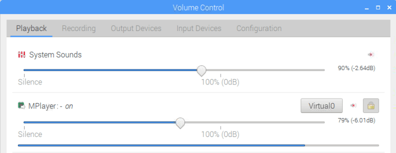
Open pavucontrol either by going to the Raspberry Pi Start Menu -> Sound & Video -> PulseAudio Volume control, or by simply typing "pavucontrol" in at the command line. Click on the Playback tab, and set MPlayer to use the "Virtual 0" audio sink.
Pulse Audio Control GUI
Fixing the Time Delay
QRP modes (especially FT8) require the computer's clock to be accurate. This is because signals are expected to be transmitted and received at specific time intervals. Most people use NTP to synchronize their computer clocks to an accurate time. Raspbian automatically syncs to NTP by default if there is an internet connection.
However, the problem is that RTL_SDR, CSDR, and mplayer all running together create an unacceptable time delay from input to output of about 2 - 3 seconds on a Pi 3. Most of the delay comes from the buffering on mplayer which helps prevent underruns when the CPU spikes. WSJT-X expects the packets to be received in the correct time frame, and will not decode them if there are more than about +/- 2 seconds out.
To fix this we need to cheat the clock a bit, and set our system time to always be a few seconds in the past. Thanks to dg0opk for letting us know about this method which involves replacing Raspbians default NTP software with Chrony which is much more configurable. Chrony should have already been installed before in the previous section, installing it automatically disables NTP and activates Chrony. Open it's config file with the following:
sudo leafpad /etc/chrony/chrony.conf
On the first command, edit it to include an offset of about -2.5 seconds.
pool 2.debian.pool.ntp.org iburst offset -2.5
Save and close the config file, then restart the Chrony server with the following.
sudo invoke-rc.d chrony restart
WSJT-X Setup
Now open WSJ-T or JTDX and in File -> Settings -> Audio tab set the Soundcard Input to be "Virtual0.monitor".
Set the Virtual0.Monitor Virtual Sound Card in WST-X
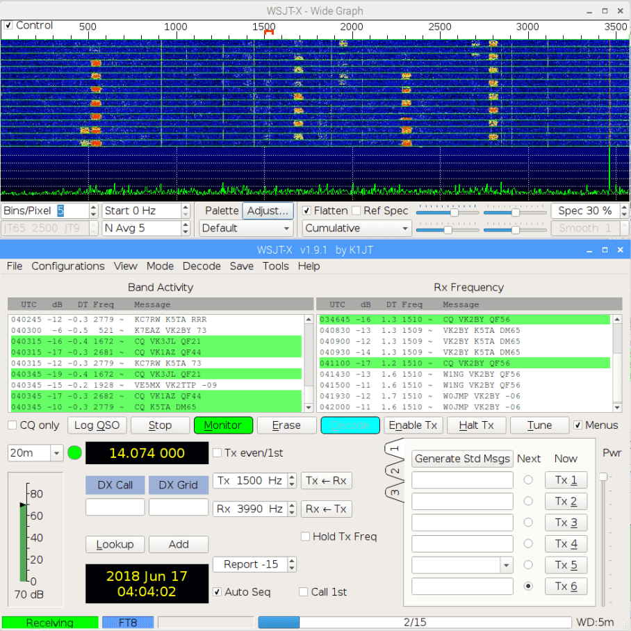
In WSJT-X set the mode to FT8, and you should now be now decoding signals as they come in.
Alternatively you could have opened JTDX instead, using "jtdx" at the terminal. The interface for setting the input sound card is identical.
WSJT-X Decoding FT8 With an RTL-SDR V3 in Direct Sampling Mode on a Pi 3
If you don't get any decodes, but are seeing signals in the spectrum, try playing with your time offset in Chrony. You should be able to see if the packets are arriving too early or too late in the WSJT-X waterfall. Once you start getting decodes, adjust the offset time accordingly to try and get the "DT" column values to as close to zero as possible. The DT column lets you know the time offset from perfect timing. E.g. -0.5 indicates that the packet was received 0.5 seconds earlier than expected.
Set up WSJT-X to Report to PSKReporter
WSJT-X can report your spots to pskreporter.info/pskmap, which is a site that aggregates QRP spots from all around the world. Here you can compare your receiver with nearby ones to see how good your antenna and setup is, and to show off how many countries you've received from.
To set it up simply enter your callsign and maidenhead grid details in the General settings of WSJT-X, and then place a check in "Enable PSK Reporter Spotting" under the Reporting tab.
If you're not a ham, you can still contribute to the site as an SWL (shortwave listener). Your callsign can be "hamprefix/SWL/city". There is an example given at https://pskreporter.info. You can find your countries hamprefix here. You can get your Maidenhead grid location from this calculator. Just use the first 4 characters it gives you.
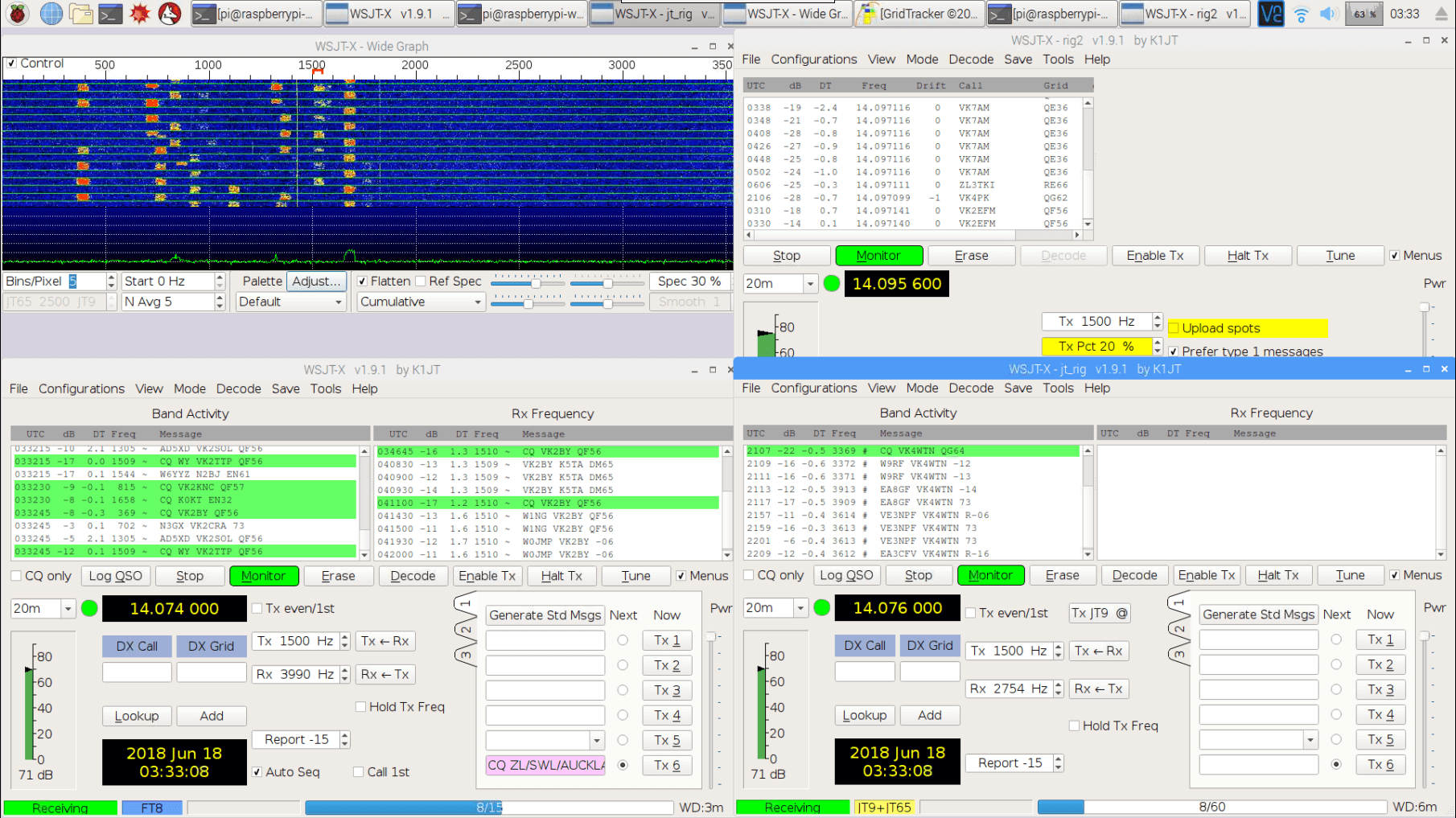
Monitoring Multiple Channels
FT8 + JT9/JT65
Here we'll show how to add simultaneous monitoring for additional QRP modes like JT65, JT9 and WSPR. First we'll show how to set up dg0opk's method that was described in his YouTube video for monitoring just FT8, JT9 and JT65. Since the JT9 and JT65 bands are only a few kHz away from FT8, we can simply open a second instance of WSJT-X, get it to listen to the same audio as the FT8 decoder, and just expand the decoding bandwidth in WSJT-X.
To do this first open a second instance of wsjt-x by typing in the terminal "wsjtx -r jt_decode".
In WSJT-X advanced settings, increase the receiver bandwidth to 4500 Hz.
Set the mode to JT9+J65, and in the waterfall window change the "JT65 2500 JT9" setting to "JT65 4500 JT9".
FT8 + JT9/JT65 + WSPR
Now to monitor WSPR, we'll need to open an actual second channel because the maximum bandwidth that WSJT-X can monitor is 6000 Hz, and WSPR is 28.1696 kHz above the FT8 frequency in the 20m band.
Open a second terminal window and run the ncat command again, making sure to change the tuned frequency. In the example below we change it to the 20m WSPR frequency of 14.0956 MHz.
Open pavucontrol either by going to the Raspberry Pi Start Menu -> Sound & Video -> PulseAudio Volume control, or by simply typing "pavucontrol" in at the command line. Here set the new player to use the "Virtual 1" audio sink.
Open a third instance of wsjt-x with "wsjtx -r wspr". Then set the input soundcard to "Virtual1.montor" and the mode to WSPR. You should be now set up.
On a Raspberry Pi 3 we've been able to successfully open and run two channels and three decoding instances of WSJT-X. If using JTDX we can really only open one or two instances due to its high CPU usage.
Grid Tracker
GridTracker is a nice piece of software that will automatically plot your spots on a map. To use it after installing it using the optional instructions further up, just run ./GridTracker from the command line.
To set up WSJT-X for GridTracker simply go into the Reporting tab of the settings window, and enable "Accept UDP Requests".
Unfortunately it seems that running GridTracker with the two channels and three decoders may be a bit too much for the Raspberry Pi 3 B CPU to handle. If you start seeing missed decodes and buffer underruns in mplayer close GridTracker.
Tips and Lessons Learned
We initially tried using sox play and aplay as the audio player. These didn't initially add any large latency, so adjusting the clock wasn't required. However, over time the players would start to display underruns every now and then. Over time the more it underran, the more the latency increased. We're not sure why. If you're running on faster hardware that never underruns, then this may be an easier solution.
FT8 is definitely the most popular mode and we recommend starting with that. JT9 and JT65 are almost dead.
Band filters can really help improve reception on the V3. You can find DIY kits from SV1AFN on eBay, or from qrp-labs.com. They require a bit of modification to add a connector however.
We've had the receiver running stable for 3 days, but the long term stability of the system hasn't been tested yet. Although dg0opk has indicated that his similar setups have been running stable for over half a year.
You must use an HF antenna. This might simply be a long length of wire (at least about 5 meters). If you're using the multipurpse dipole kit from our RTL-SDR V3 set, then you'll need to extend the length of the arms for HF using two lengths of wire. Simply clamp on about 5 meters or more wire to each leg of the dipole.
We used a Raspberry Pi 3B. The newer 3B+ may offer improved performance. Overclocking the Pi may also help.
Over on Hackaday.io, project logger Humpelstilzchen has been writing about his attempts to create an autonomous RF direction finding robot RC car with an RTL-SDR. The goal is to set up an ISM band transmitter as a beacon, and use the RTL-SDR on the robot as the receiver. It will then use direction finding techniques to drive towards the beacon. The robot is a 4WD RC toy car with some autonomous navigational features like GPS, ultrasonic, IMU and vision sensors.
In his latest project log Humpelstilzchen describes his first semi-successful attempt at getting RF direction finding working. In the experiment he uses a 433 MHz module to send out an FSK beacon. On the robot two antennas are used for the time difference of arrival/pseudo-doppler direction finding technique, and PIN diodes are used to rapidly switch between the antennas. A GNU Radio script running on a HummingBoard single board computer computes the TDOA/pseudo-doppler algorithm.
Psuedo-doppler direction finding works by rapidly switching between several antennas. The difference in the time that the signal arrives at each antenna can be used to calculate the transmitter's direction.
With the current set up he's been able to get the robot to distinguish if the beacon is closer to the left, or closer to the right, or equidistant. However, he notes that there are still problems with reflections of the beacon signal which can cause the robot to drive in the wrong direction.
This is still a work in progress and we look forward to his future results.
Thanks to the work of Lucas Teske, GQRX is now able to connect to SpyServer servers. SpyServer is the IQ streaming server software solution developed by the Airspy SDR developers. It can support Airspy and RTL-SDR devices, and can be used to access these SDRs remotely over a network connection. It is similar to rtl_tcp, but a lot more efficient in terms of network usage, meaning that it performs well over an internet connection. On a previous post we have a tutorial about setting up a SpyServer with an RTL-SDR.
The code modified by Lucas is the gr-osmosdr module, and Lucas' code can be downloaded from his GitHub at github.com/racerxdl/gr-osmosdr. It doesn't yet appear to have been merged into the official osmocom branch. The gr-osmosdr module is a generic block used to access various SDR hardware, so any software that utilizes it (such as GNU Radio) should be able to connect to a SpyServer connection too.
Just a note that the website for the popular NOAA APT weather satellite decoding software WxtoImg is currently down, and may possibly never be revived. This software is commonly used with RTL-SDR dongles to download weather satellite images from the NOAA 15, 18 and 19 polar orbiting satellites.
It seems that the author of the software has not been maintaining the site and software for a while, although there was a brief update on the site back in 2017 when the professional version keys were released for free. But the keys reportedly no longer work. WXtoImg is closed source, so the code is not available either.
Some of the downloads are still available via archive.org, however it only seems to be the Windows and some of the Linux versions that were archived. Over on two Reddit threads [1] [2], some users are also collecting the last free versions and making them available for download again. If anyone has access to the last beta versions for ARM devices please upload them somewhere too.
Also if anyone happens to have the contact details of the author, or someone who knows the author please let us know as we'd like to ask for permission to mirror the files.
Over on YouTube w2aew who has many excellent videos explaining various radio topics has uploaded a new video that talks about the basics of bias tees, and shows some applications and examples. In the video he demonstrates using a bias tee to add DC voltage to a serial signal, measure the RF performance of a BJT transistor, and to tune a remotely tunable 'screwdriver' antenna.
On receiver radios bias tees are commonly used to power remote LNA's (low noise amplifiers) or active antennas by putting DC power onto the coax cable. Ideally an LNA should be placed closer to the antenna as this will help reduce the loss caused by coax cable. Often the antenna is far away from the receiver on a roof or attic where there is no power supply. A bias tee solves that by allowing the coax cable to be used for DC power.
We note that our RTL-SDR Blog V3 dongle has a built in bias tee that can be activated in software.
#284: Basics of RF Bias Tees including applications and examples