The uBITX is a US$129 HF SSB/CW QRP transceiver kit that works from 3 MHz to 30 MHz with up to 10W TX power. It's a fully analogue radio, but it can be combined with an RTL-SDR to create a panadapter display thanks to a tutorial released by KD8CEC.
The method requires that you use the custom CEC firmware, or modify other firmware, as this appears to change the output frequency at the tap point. The tap point is made accessible by soldering on an extra SMA connector for the RTL-SDR to connect to. The rest of the work is entirely performed in the uBITX software manager, Omni-Rig and SDR-Console V3.
FPV stands for 'First Person View', and is a term used to describe the hobby of flying remote controlled aircraft entirely via the view from a wireless camera that transmits live video to the pilots screen or video goggles.
Part of the FPV hobby is to not only enjoy flying, but also to tweak the wireless video equipment for maximum range and reliability. This involves measuring the SWR characteristics of FPV antennas. SWR is a metric that describes how well the impedance of an antenna is matched with the receiver at a certain frequency. Poor SWR results in additional signal loss on top of cable and connector loss. We note that SWR is only one antenna metric, and doesn't take into account radiation pattern and antenna gain which is often more important, but it is the easiest metric to measure and control, and should give you some idea as to if an antenna was designed and tuned properly.
As FPV hobbyists are often not hams or radio professionals, most don't have access to the equipment required to measure SWR. So over on his YouTube channel bonafidepirate shows how he's been using a cheap RTL-SDR, noise source and RF Bridge to measure the SWR of his FPV antennas. The process is similar to the one shown in our tutorial, but he uses the Spektrum software which allows you to measure SWR entirely within the software itself.
In the video bonafidepirate goes over the required hardware, software and the setup, and then demonstrates several SWR scans of different FPV antennas.
Recently Akos has uploaded three new posts on his RadioForEveryone blog. The first post is a review of the "Ham-It-Up Plus", which is a US$65 upconverter that allows you to listen to HF on RTL-SDR dongles without direct sampling. Compared to the non-plus Ham-It-Up, the plus version includes a TCXO and the noise source circuit is populated. In his post Akos reviews the history of the Ham It Up generations and discusses the connectors and power options. He also reviews the performance and finds that the Plus seems to have better SNR.
In the second post Akos has uploaded his collection of various images of different RTL-SDR dongle brands. The images include circuit board photos so you can easily compare the differences in design between brands.
Finally the third post is an experiment to determine the maximum USB cable length that can be used with RTL-SDRs. His results show that the maximum is 9 meters which is actually more than the USB2.0 spec which states 5m as the maximum. We note that longer than 9m cable runs can also be achieved by using active repeater USB cables or USB hubs.
Over on YouTube, Alexander from the Russian channel РАДИОБЛОГ с Александром Никитенко has uploaded a video review of a Russian USB filter product, designed for USB SDR dongles. The video is narrated in Russian, however you can use the YouTube auto-translate feature to get somewhat understandable subtitles. The actions he takes in the video are also easy to understand.
The USB filter is designed by Maxim who runs a small company called ExpElectroLab. Back in August we posted about another ExpElectroLab product which was the SDR# tuning knob. Since then we've seen that a few people outside of Russia have been able to order the product by contacting him at eel.radiohelp@gmail.com, and have been happy with it.
When using USB SDR dongles, the USB cable can pick up lots of interference from the PC and monitors, providing a direct path for this interference to enter the RTL-SDR. A USB filter can be used to remove this interference. There are several USB filters on the market designed for improving USB audio devices, but this is the first one we've seen designed for SDRs in particular.
In the video Alexander tests an RTL-SDR with and without the USB filter connected. With the USB filter not connected, the SDR# display shows several spikes of interference in the spectrum, and once the filter is connected these spikes disappear. He also tests it on a USB powered shortwave radio, and the filter appears to remove the hiss caused by the power supply.
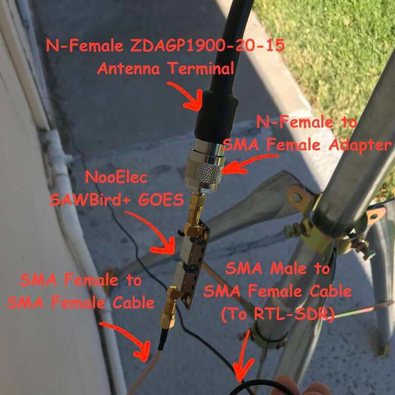
Aleksey Smolenchuk (lxe) has recently uploaded a step-by-step guide to setting up a GOES weather satellite receiver with an RTL-SDR dongle, Raspberry Pi and the goestools software. GOES 15/16/17 are geosynchronous weather satellites that beam high resolution weather images and data. In particular they send beautiful 'full disk' images which show one side of the entire earth. Compared to the more familiar and easier to receive low earth orbit satellites such as NOAA APT and Meteor M2 LRPT, the geosynchronous GOES satellites require slightly more effort as you need to set up a dish antenna, use a special LNA, and install Linux software.
Aleksey's tutorial first shows where to purchase the required hardware and notes that the total cost of the system is around $185. Next he goes on to show the hardware connection order, and then how to install and configure the goestools decoding software onto a Raspberry Pi.
Over on YouTube user aonomus has uploaded a video showing how he's used an RTL-SDR to observe and listen to the radio signal generated via a chemistry lab's nuclear magnetic resonance machine. To do this he simply taps the RF output of the NMR machine which allows the RTL-SDR to listen to the signal and play it as audio. In the video he shows the sound of a sample of chloroform in acetone-d6. The demo has no real scientific purpose other than to hear the sound of the molecule. Normally the RF output goes straight into a spectrum analyzer for visual analysis.
Nuclear magnetic resonance is a technique used in chemistry for the analysis of chemicals, as well as in MRI medical imaging machines. Very basically, it works by applying a chemical sample to a strong magnetic field, exciting it with a strong pulse of RF, and listening to the echo. An echo will only occur when the radio waves are transmitted at the chemicals resonant frequency. The frequencies used are typically between 60 to 800 MHz.
A few years ago I came up with a demonstration for some high school students interested in chemistry. This demo is a modern take on a classic NMR experiment, using a low cost software defined radio to observe the FID signal as audio. In short, this demo allows you to hear the proton FID echo from the liquid sample inside the NMR magnet.
Nuclear Magnetic Resonance Demonstration Using Software Defined Radio
Thank you to Josh for submitting news about his project called GammaRF. GammaRF is an client-server program that is used to aggregate signal information via the internet from distributed SDRs. Currently the RTL-SDR and HackRF SDRs are supported.
ΓRF (“GammaRF”, or “GRF”) is a radio signal collection, storage, and analysis system based on inexpensive distributed nodes and a central server. Put another way, it is a distributed system for aggregating information about signals, and a back-end infrastructure for processing this collected information into coherent “products”.
Nodes utilize inexpensive hardware such as RTL-SDR and HackRF radios, and computers as small and inexpensive as Intel NUCs. Each node runs modules which provide various radio monitoring functionality, such as monitoring frequencies for “hits”, watching power levels, keeping track of aircraft (through ADS-B), and more. Nodes are distributed geographically and their data is combined on the server for hybrid analysis.
A web-based system allows users to view information from and about each station in its area. Below shows the server landing page. Markers are placed at each station’s last known location (stations can be mobile or stationary.)
GammaRF Server Landing Page
From the currently implemented modules it appears that you can monitor ADS-B, scan and monitor the power of a set of frequencies, forward the output from trunk-recorder (a P25 call recorder), scan the spectrum and monitor power levels, monitor a single frequency for activity, take a picture of a swath of RF spectrum, and collect 433 MHz ISM data. Some example applications might include:
Monitoring ham radio activity on repeaters in a city
Creating timelines of emergency services activity in an area
Distributed tracking of satellites and other mobile emitters
Monitoring power at a frequency, for example as a mobile node traverses an area (e.g. signal source location)
Building direction finding networks (e.g. for fox hunts)
Spectrum enumeration (finding channels and guessing modulation) [under development]
Monitoring Activity of an Amateur Radio Repeater via the 'scanner' Module
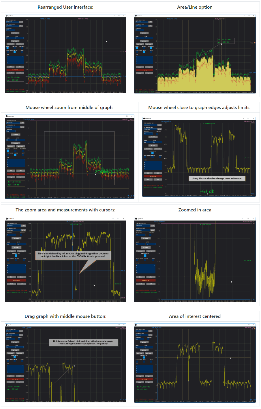
Spektrum is a popular spectrum analyzer program that is used with RTL-SDR dongles. It is based on the command line rtl_power software and is compatible with both Windows and Linux. Thanks to it's easy to use GUI it is an excellent piece of software for scanning and determining where active signals exist, or for measuring filters and antenna SWR with a noise source.
Recently SV8ARJ (George) and SV1SGK (Nick) have been working on extending the original open source Spektrum code. Their improvements focus around the UI and making it more functional and easier to use. Currently the updated branch is in alpha, and they are hoping that any testers could help report bugs, issues and wishes to them. The code is available on their GitHub and the latest Windows test build can be downloaded from their DropBox.
The changelog reads:
2 Cursors for Frequency axis.
2 Cursors for Amplitude axis.
Absolute and differential measurements with cursors.
Zoom functionality of the cursors's defined area (gain + frequency).
Mouse Wheel Gain adjustment on graph (Top area for upper, low area for lower).
Mouse Wheel Frequency adjustment on graph (left area for lower frequency, right for upper).
Mouse Wheel in the centrer of the graph performs symetric zoom in/out.
View/settings store/recall (elementary "back" operation, nice for quick zoomed in graph inspection).
Right click positions primary cursors.
Right Double Click positions primary cursors and moves secondary out of the way.
Left Double Click zooms area defined by cursors (Amplitude + frequency).
Left Mouse Click and Drag on a cursor moves the cursor.
Middle (mouse wheel) Double Click resets full scale for Amplitude and Frequency.
Middle (mouse wheel) Click and Drag, moves the graph recalculating limits accordingly.
Reset buttons to Min/Max range next to Start and Stop frequency text boxes.
Cursor on/off checkbox now operate on all 4 cursors.
ZOOM and BACK buttons.
Filled-in graph option (line or area).
Display of frequency, Amplitude and differences for all cursors.
Modified: Button layout.
Fixed: Save/Reload settings on exit/start. IMPORTANT : delete the "data" folder from the installation location if you have it.
KerberosSDR is our upcoming low cost 4-tuner coherent RTL-SDR. With four antenna inputs it can be used as a standard array of four individual RTL-SDRs, or in coherent applications such as direction finding, passive radar and beam forming. More information can be found on the KerberosSDR main post. Please remember to sign up to our KerberosSDR mailing list on the main post or at the end of this post, as subscribers will receive a discount coupon valid for the first 100 pre-order sales. The list also helps us determine interest levels and how many units to produce.
In this post we're showing some more passive radar demos. The first video is a time lapse of aircraft coming in to land at a nearby airport. The setup consists of two DVB-T Yagi antennas, with KerberosSDR tuned to a DVB-T signal at 584 MHz. The reference antenna points towards a TV tower to the west, and the surveillance antenna points south. Two highlighted lines indicate roughly where reflections can be seen from within the beam width (not taking into account blockages from mountains, trees etc).
The second video shows a short time lapse of a circling helicopter captured by the passive radar. The helicopter did not show up on ADS-B. On the left are reflections from cars and in the middle you can see the helicopter's reflection moving around.
We are expecting to receive the final prototype of KerberosSDR within the next few weeks. If all is well we may begin taking pre-orders shortly after confirming the prototype.
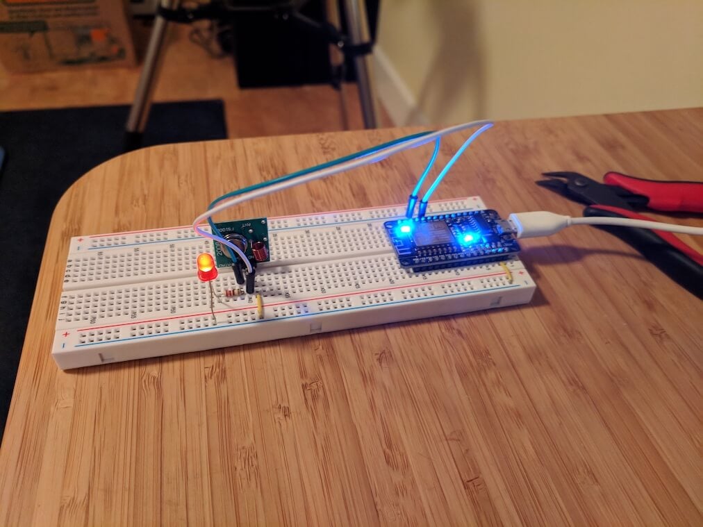
Amazon Alexa is a smart speaker that can be programmed to control home automation devices via voice commands. For example, Stuart Hinson wanted to be able to control his wirelessly controlled blinds simply by verbally asking Alexa to close or open them. Stuart's blinds could already be controlled via a 433 MHz remote control, so he decided to replicate the control signals on an ESP8266 with 433 MHz transmitter, and interface that with Alexa. The ESP8266 is a cheap and small WiFi capable microchip which many people are using to create IoT devices.
Fortunately replicating the signal was quite easily as all he had to do was record the signal from the remote control with his RTL-SDR, and use the Universal Radio Hacker software to determine the binary bit string and modulation details. Once he had these details, he was able to program the ESP8266 to replicate the signal and transmit it via the 433 MHz transmitter. The remaining steps were all related to setting up an HTTP interface that Alexa could interface with.
If you're interested, we've also previously posted about another Alexa + RTL-SDR mashup which allows Alexa to read out ADS-B information about aircraft flying in your vicinity.
VOR stands for VHF Omnidirectional Range and is a way to help aircraft navigate by using fixed ground based beacons. The beacons are specially designed in such a way that the aircraft can use the beacon to determine a bearing towards the VOR transmitter. VOR beacons are found between 108 MHz and 117.95 MHz, and it's possible to view the raw signal in SDR#.
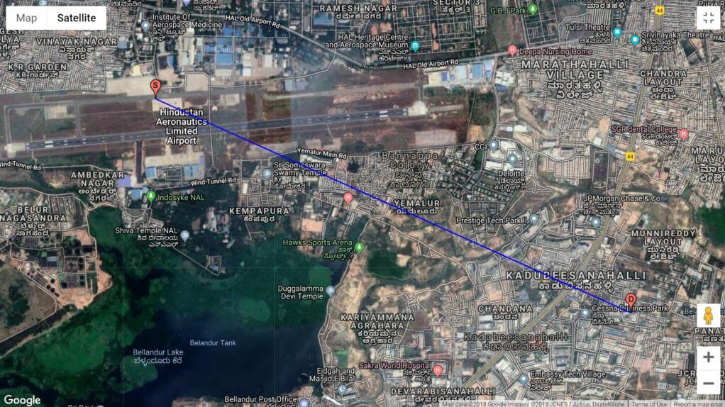
Over on RadioJitter author Arnav Mukhopadhyay has uploaded a post describing how to decode VOR into a bearing in real time using an RTL-SDR dongle. His post first explains how VOR works, and then goes on to show an experimental set up that he's created using a GNU Radio program. With the software he was able to decode an accurate bearing towards the VOR transmitter at a nearby airport.
Arnavs post is a preview of an academic paper that he's worked on, and the full paper and code is available by request on the radiojitter post. We've also seen on YouTube that Arnav has uploaded a video showing the software working in action, and we have embedded it below.
Bearing to nearby airport VOR transmitter determined with an RTL-SDR and GNU Radio.
Over on YouTube user Petr Horký has uploaded a helpful tutorial video showing how to install GNU Radio on Windows 10. Petr goes through the steps from installing Python, pip and other dependencies like numpy and pyqt, to installing GNU Radio itself and then ensuring that the system PATH is set correctly.
GNU Radio is a block based programming language for building digital signal processing applications (e.g. demodulators/decoders). It is very useful for experimenting with more advanced SDR concepts, and there are also many RTL-SDR compatible applications built with GNU Radio as well. GNU Radio is typically run on Linux, but can also run on Windows now too, although perhaps not every program will be compatible.
How to install GNU Radio Companion on Windows 10 (pip, environment variables)
RPiTX is software for the Raspberry Pi which can turn it into a 5 kHz to 1500 MHz transmitter which can transmit any arbitrary signal. In order to transmit the software does not require any additional hardware apart from a wire plugged into a GPIO pin on the expansion header. It works by modulating the GPIO pin with square waves in such a way that the desired signal is generated. However, although additional hardware isn't required, if RPiTX is to be used in any actual application a band-pass filter is highly recommended in order to remove any harmonics which could interfere and jam other radio systems.
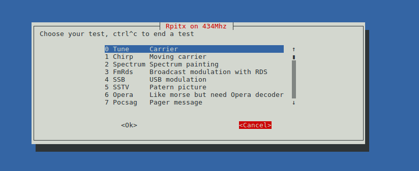
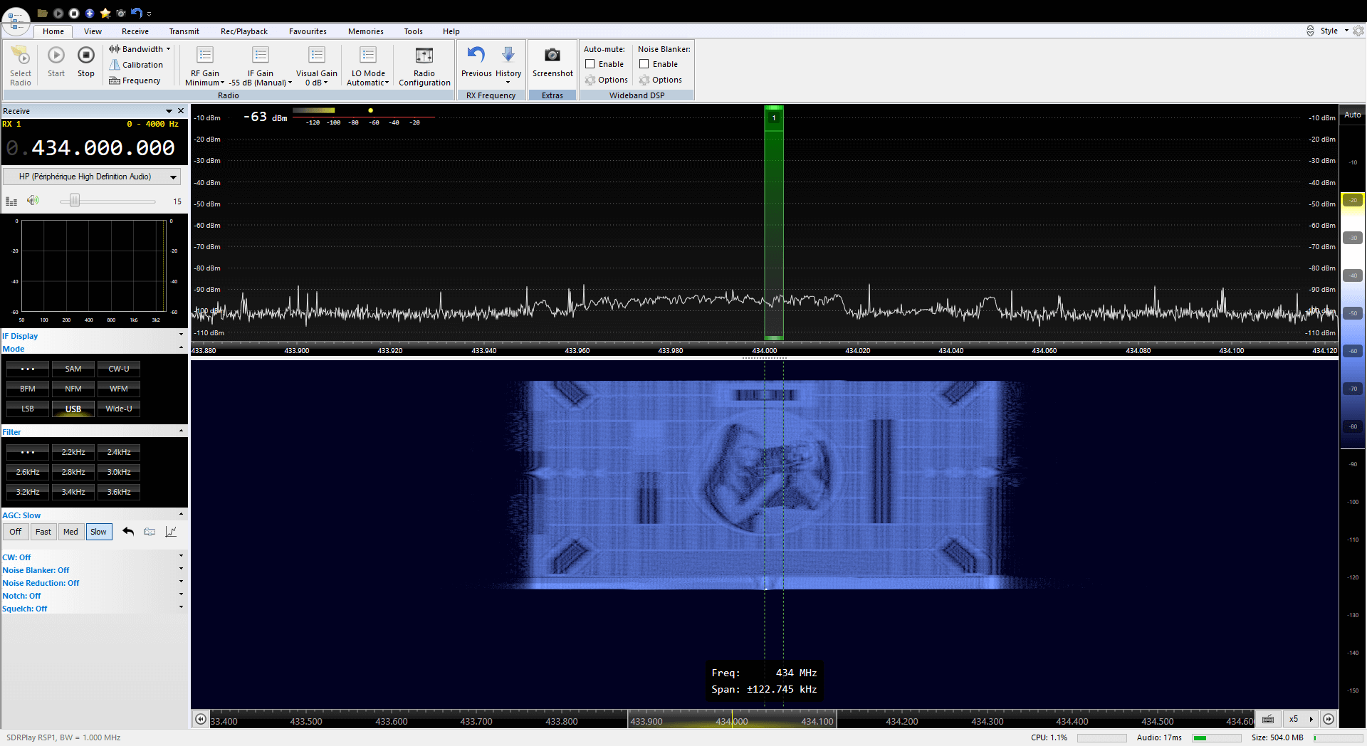
Earlier this month RPiTX was upgraded to version 2. One of the changes is a new GUI for testing the various transmission modes. Currently it is possible to transmit a chirp, FM with RDS, USB, SSTV, Opera, Pocsag, SSTV, Freedv. There is also a spectrum painter which allows you to display an image on a SDR's waterfall.
The RPiTX V2 GUIPainting an Image on a SDR Waterfall Display with RPiTX v2
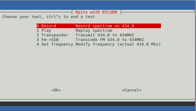
The RPiTX v2 update also makes recording a signal with an RTL-SDR, and replaying that signal with RPiTX significantly easier. Previously it was necessary to go through a bunch of preprocessing steps (as described in our previous tutorial) in order to get a transmittable file, but now RPiTX is capable of transmitting a recorded IQ file directly. This makes copying things like 433 MHz ISM band remotes significantly easier. One application might be to use RPiTX as an internet connected home automation tool which could control all your wireless devices.
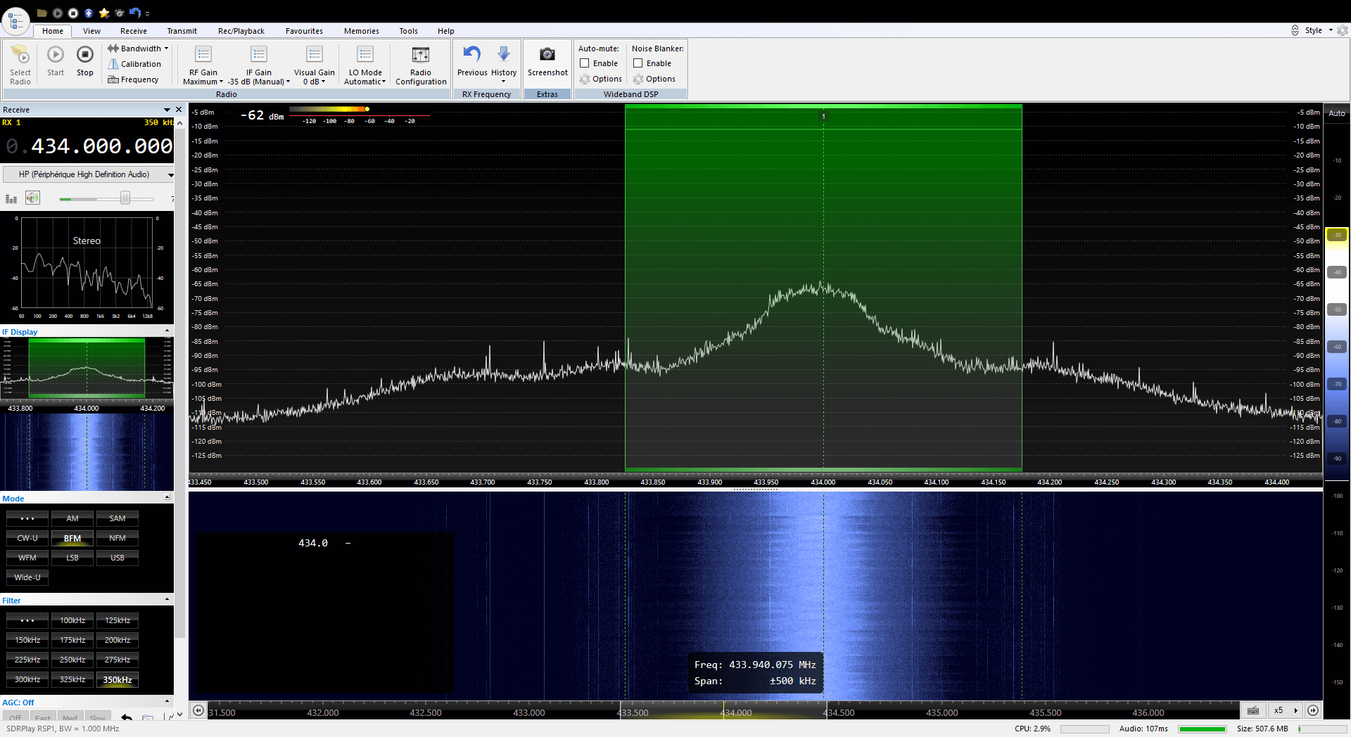
Finally, another application of the RPiTX and RTL-SDR combination is a live RF relay. The software is able to receive a signal at one frequency from the RTL-SDR, and then re-transmit it at another frequency in real time. Additionally, it is also capable of live transmodulation, where it receives an FM radio station, demodulates and then remodulates it as SSB to transmit on another frequency.
The RPiTX V2 RTL-SDR MenuRPiTX v2 re-transmitting a broadcast FM signal live at 434 MHz.
Over on YouTube Fuzz The Pi Guy has uploaded a video tutorial showing how to set up a Broadcastify air traffic control audio feed with RTL-Airband and an RTL-SDR running on a Raspberry Pi. This allows you to publicly share your received air traffic control audio online via sites like Broadcastify.
The video is based on a comprehensive Radioreference text tutorial which takes you through the process from scratch. Setting it up involves installing the Raspbian OS, installing RTL-SDR, installing and setting up RTL-Airband, configuring ezstream and then ensuring that everything runs automatically on boot. It's a fairly involved setup process, but the video helps make things easier.
How To Setup Broadcastify On A Raspberry Pi Using RTL_AM For Aviation
Over on YouTube icholakov has uploaded an informative video that gives an overview of the main communication modes that aircraft use from HF to UHF. In the video he also gives examples of those modes being received and decoded with an SDR.
The modes that he explains and demonstrates are VHF voice, VHF ATIS automated weather, ACARS short data messages, HF voice, HF automatic weather, HF data selective calling (SELCAL), HF data link (HFDL) and UHF ADS-B aircraft positioning.
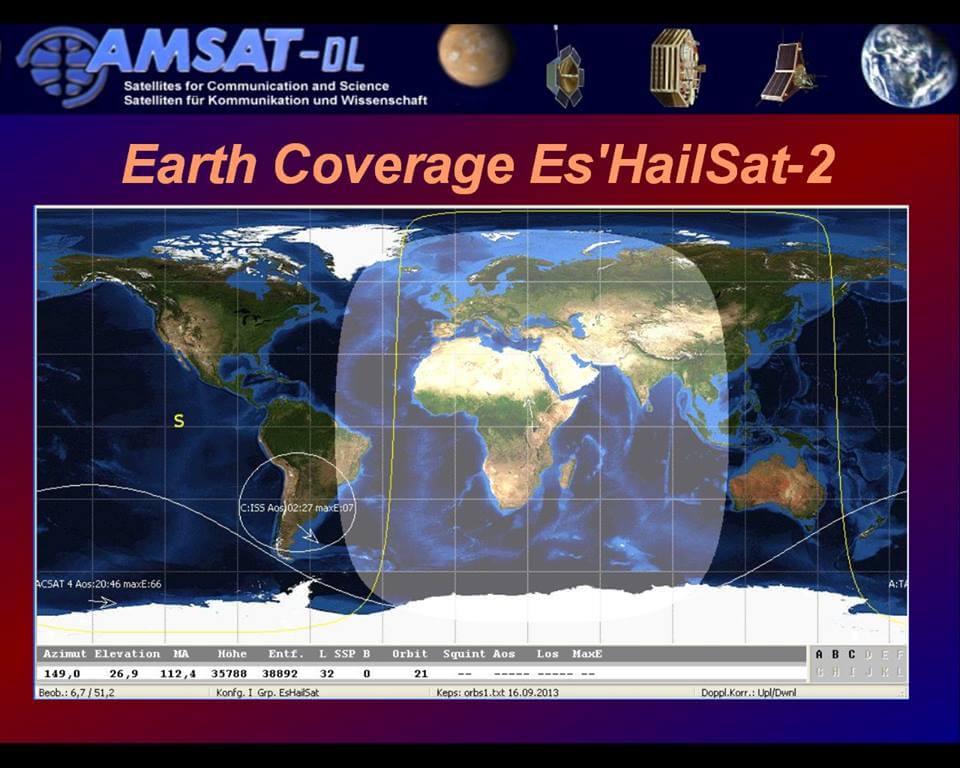
Today SpaceX have successfully launched and deployed the Es'hail-2 satellite which is now in geostationary orbit. This launch is special for amateur radio enthusiasts because it is the first geostationary satellite that contains an amateur radio transponder on it. The satellite is positioned at 25.5°E which is over Africa. It will cover Africa, Europe, the Middle East, India, eastern Brazil and the west half of Russia/Asia. Unfortunately, North America, Japan, most of South America, Australia and NZ miss out.
Coverage of Es'hail 2
The satellite has a two bandwidth segments, a 250 kHz narrow band for modes like SSB, FreeDV, CW, RTTY etc, and a 8 MHz wide band for digital amateur TV (DATV) modes like DVB-S and DVB-T.
The downlink frequencies are at 10 GHz so a low cost TV LNB could be used as the antenna. For receiving the narrowband modes, an RTL-SDR or similar SDR could be used, and for the 8 MHz DATV modes a standard DVB-S2 set top box can be used to receive and decode the video. For uplink, the transmission frequency is at 2.4 GHz.
According to the commissioning order of the satellite, it is expected that the AMSAT transponders will be activated only after all tests have been passed, and after other higher priority commercial telecommunications systems have been activated. This is expected to take about 1-2 months.
2018: Es'hail-2 and its amateur radio payload - Graham Shirville (G3VZV) & Dave Crump (G8GKQ)
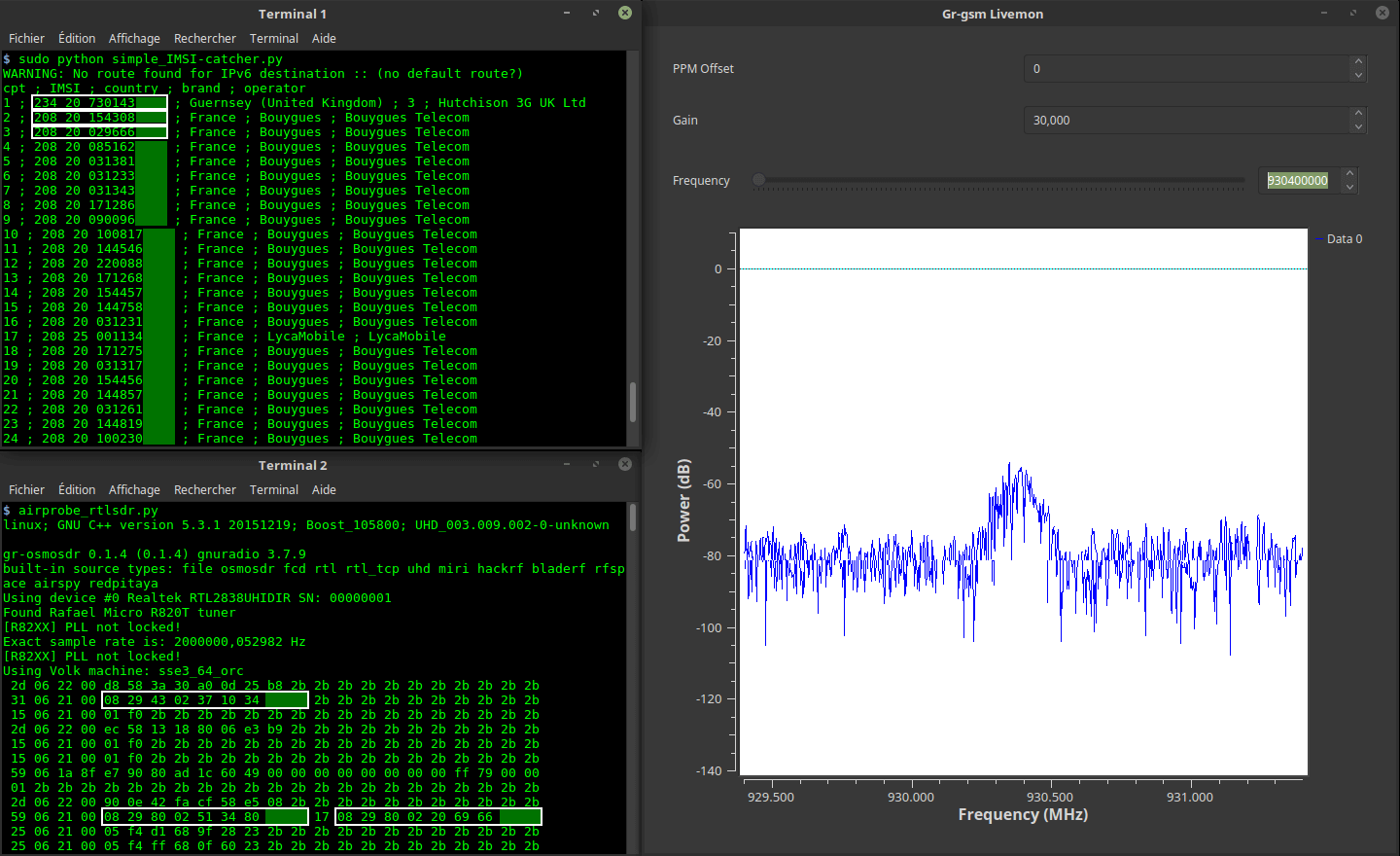
Motherboard, an online technology magazine has recently run an article titled "With $20 of Gear from Amazon, Nearly Anyone Can Make This IMSI-Catcher in 30 Minutes". The article describes how an RTL-SDR together with the IMSI-Catcher Linux software can be used to collect IMSI numbers from cellphones connected to a nearby cell tower. The IMSI is a unique number assigned to each SIM card and collecting this data could be used to identify if someone is in the area covered by the cell tower.
The IMSI-Catcher software only works with the older 2G GSM signals which are now being phased out in some countries and are relatively unused in others. Also unlike more advanced IMSI-Catchers which create a fake cell tower signal, the RTL-SDR based IMSI-Catcher can only collect IMSI numbers when the cellphone first connects to the cell tower.
Thank you to Thierry Leconte (TLeconte) for writing in and submitting his new command line based open source software called vortrack. Vortrack is a simple VOR decoder which calculates the angle towards the VOR. It is compatible with both RTL-SDR and Airspy radios, and runs on Linux.
In the past we've seen several other posts about RTL-SDRs being used to decode VOR signals, but Thierry's implementation appears to be the easiest way to get a bearing straight away. You'll get the most use out of the software if you install it on a portable device like a Raspberry Pi and take it out for a drive as you'll be able to see the VOR angle changing then.
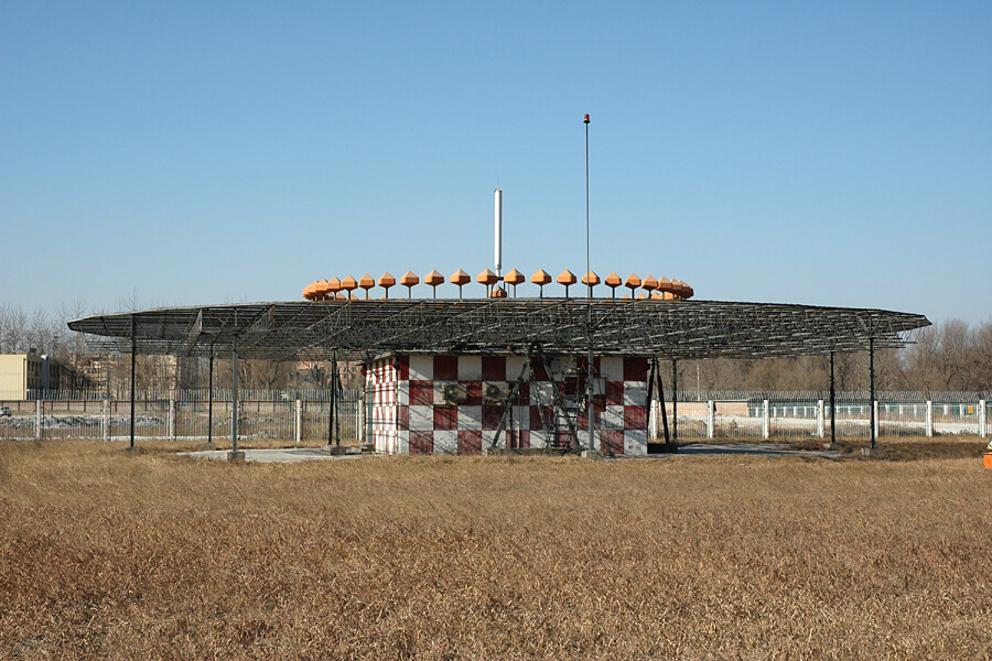
VOR stands for VHF Omnidirectional Range and is a way to help aircraft navigate by using fixed ground based beacons. The beacons are specially designed in such a way that the aircraft can use the beacon to determine a bearing towards the VOR transmitter. VOR beacons are found between 108 MHz and 117.95 MHz, and it's possible to view the raw signal in SDR#.
A DVOR Ground Station at an Airport. Source Wikipedia.
In his post K2GOG mentions our successfully crowd funded KerberosSDR which will be shipping in January next year. KerberosSDR is our 4x coherent RTL-SDR, and one possible application is to use it as a four antenna phase coherent direction finder. K2GOG explains the phase coherent concept in his post quite elegantly.
While looking over KerberosSDR, K2GOG was also reminded of another direction finding technique called heat mapping which can be performed with a single RTL-SDR. This process involves driving around with an RTL-SDR and GPS logger, measuring the signal power as you drive and combining it the current GPS coordinates. From that data a heat map can be generated, which shows where the signal is the strongest, and therefore where the likely source is. The RTLSDR Scanner application by eartoearoak makes doing this easy, and in his post K2GOG provide a short tutorial on setting it up.
A heatmap generated by K2GOG with an RTL-SDR, GPS and RTLSDR Scanner.
Over on YouTube, channel Null Byte has uploaded a video showing us how to use an RTL-SDR V3 on an Android smartphone. In the video he discusses the hardware and software required to get started on Android and demonstrates the free SDRoid Android app (based on RFAnalyzer) by tuning to several signals including a voice signal. Later in the video he also shows an ADS-B app for receiving aircraft positions. The video is intended for people new to RTL-SDR so it is a little basic, but it's a great introduction.
He notes that the next video (which will probably be released in a week) will show RPiTX being used with the RTL-SDR.
Use an RTL-SDR Software-Defined Radio Receiver with an Android Smartphone [Tutorial]