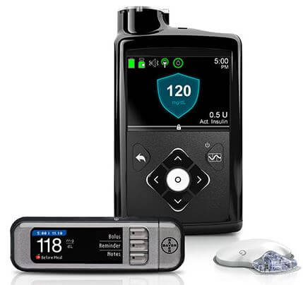
Recently Arstechnica ran a story about how during this August's Black Hat security conference, researchers Billy Rios and Jonathan Butts revealed that a HackRF software defined radio could be used to withhold a scheduled dose of insulin from a Medtronic Insulin Pump. An insulin pump is a device that attaches to the body of a diabetic person and deliveries short bursts of insulin throughout the day. The Medtronic Insulin Pump has a wireless remote control function that can be exploited with the HackRF. About the exploit MiniMed wrote in response:
In May 2018, an external security researcher notified Medtronic of a potential security vulnerability with the MiniMedTM Paradigm™ family of insulin pumps and corresponding remote controller. We assessed the vulnerability and today issued an advisory, which was reviewed and approved by the FDA, ICS-CERT and Whitescope.
This vulnerability impacts only the subset of users who use a remote controller to deliver the Easy Bolus™ to their insulin pump. In the advisory, as well as through notifications to healthcare professionals and patients, we communicate some precautions that users of the remote controller can take to minimize risk and protect the security of their pump.
As part of our commitment to customer safety and device security, Medtronic is working closely with industry regulators and researchers to anticipate and respond to potential risks. In addition to our ongoing work with the security community, Medtronic has already taken several concrete actions to enhance device security and will continue to make significant investments to improve device security protection.
In addition to this wireless hack they also revealed issues with Medtronic's pacemaker, where they found that they could hack it via compromised programming hardware, and cause it to deliver incorrect shock treatments.
Earlier in the year we also posted about how an RTL-SDR could be used to sniff RF data packets from a Minimed Insulin pump using the rtlmm software, and back in 2016 we posted how data could be sniffed from an implanted defibrillator.
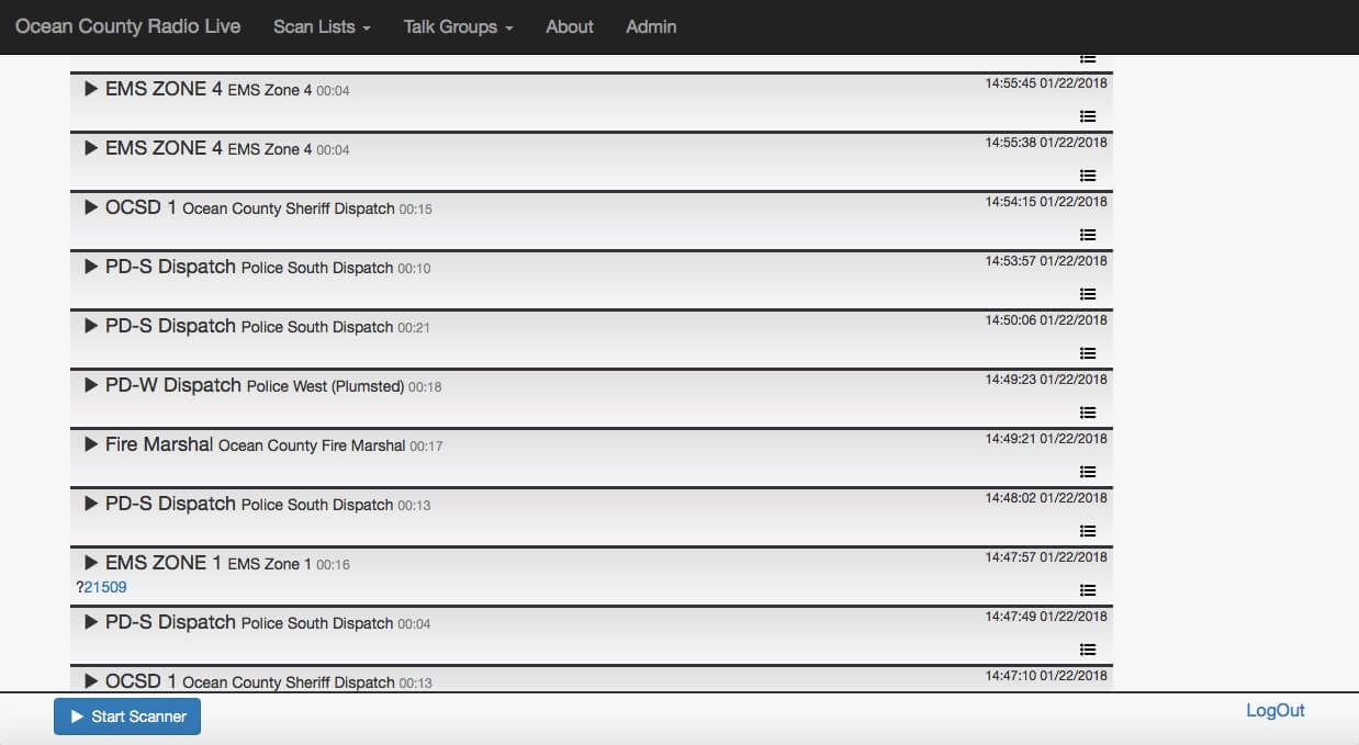
During the Cyberspectrum Wireless Village talks a few days ago Gavin Rozzi gave a talk about his online RTLSDR-based trunking scanner website at ocradio.live. Recently he wrote in and wanted to share a little more about his system. He writes:
[The talk focuses] on my experience implementing several open source software packages to create an online RTLSDR-based trunking scanner website, https://ocradio.live/ that serves the part of New Jersey that I live in. Using multiple RTLSDR receiving locations, the site is demodulating, recording, and timeshifting multiple talkgroups of local and state trunked radio systems to create a live streaming service and archive of past scanner calls. Data from the site is also accessible over a REST API and we allow the creation of custom scan lists. My presentation is going to center on the advantages the site has over traditional hardware scanners and some of the technical challenges that we had to overcome to get the project off the ground.
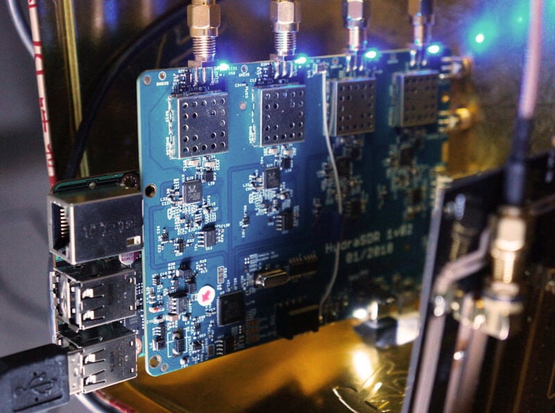
Over the last few months we've been working on a 4-input coherent RTL-SDR called 'HydraSDR' that is designed to be a low cost way to get into applications such as RF direction finding, passive radar, beam forming and more. It can also be used as a standard 4-channel SDR for monitoring multiple frequencies as well.
Phase coherent RTL-SDRs have been worked on and demonstrated several times over the past few years, but we've been disappointed to find that so far there hasn't been any easy way to replicate these experiments. The required hardware has been difficult to build and access, and the software has been kept as unreleased closed source or has been too complicated to install and use. With HydraSDR we aim to change that by making phase coherent applications easier to access and run by providing ready to use hardware and software.
Thanks to our developer Tamás Peto, a PhD student at Budapest University of Technology and Economics whom we hired via the ad in our previous post, and the Othernet (formerly Outernet) engineering team who are our partners on this project, we've been able to build a working system, and demonstrate coherent direction finding and passive radar working as expected (demo videos below). We plan to eventually release Tamás' code as open source so that the entire community can benefit and build on it. Also if HydraSDR turns a profit, we plan to reinvest some of the profits into continually improving the software and expanding the list of use cases.
At the moment we are finalizing our prototype, and plan to begin final production within the next 2-3 months.
If you have any interest in HydraSDR, please sign up to our Hydra mailing list. This will help us gauge how many units to produce and will affect the final pricing. If you've already signed up to our weekly posts list, please sign up to this list too as it's a different list. Subscribers to this list will be the first to know when Hydra goes on preorder, and the first 100 sales will receive a discounted price. We expect to begin taking preorders in within a month and to ship 1-2 months after preorders begin.
Direction Finding
HydraSDR can be used to find the bearing towards a signal using it's coherent direction finding capabilities. The software by Tamás currently implements several direction finding algorithms such as Bartlett, Capon, Maximum Entropy (MEM) and MUSIC. In the video below we show a quick test of the direction finding system working with a HackRF being used as a signal source, and four dipole antennas connected to HydraSDR in a linear array. The MUSIC algorithm is used.
HydraSDR Direction Finding Test
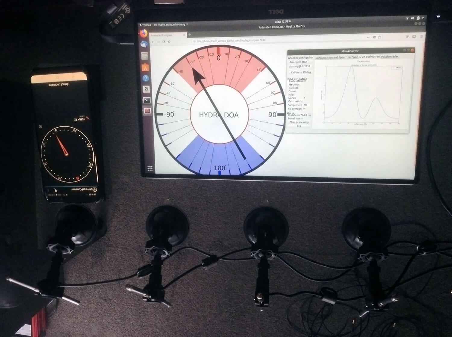
In the image below we also attempted to find the direction towards a known TETRA transmitter. We were able to confirm the direction with an Android compass app that points towards the known transmitter location. As the two angles match, we can be confident that Hydra is finding the correct direction to the transmitter.
Finding the direction of a TETRA Transmitter
Passive Radar
HydraSDR can also be used for passive radar. Normal radar systems work by transmitting a pulse of RF energy, and listening to the reflections from objects like planes, cars and ships. Passive radar works by using already existing transmitters such as those for FM/TV and listening for reflections that bounce of objects.
With a simple passive radar system you need two directional antennas and two coherent receivers. One antenna points at the transmitting 'reference' tower, and the other at the 'surveillance' area where you want to listen for reflections. It's important to try and keep as much of the reference signal out of the surveillance antenna as possible, which is why directional antennas like Yagi's are used.
The result is a doppler vs time delay graph, where the reflection of aircraft, cars, ships and other objects can be seen. The doppler gives you the speed of the object relative to your antenna and the transmitting tower, and the time delay gives you the distance relative to your antenna and the transmitter tower.
Below is an example time lapse video of HydraSDR being used for passive radar. The reference antenna points towards a DVB-T transmitter at 588 MHz, and the surveillance antenna overlooks a small neighborhood, with aircraft sometimes flying over. The antennas we used were two very cheap TV Yagis.
You can constantly see the reflections from vehicles at small doppler values (low speeds), and every now and then you see an aircraft reflection which shows up at much higher doppler (speed) and further time delay (distance) points.
HydraSDR Passive Radar Timelapse Test 1
More information about HydraSDR
HydraSDR includes:
4x Coherent R820T2 based RTL-SDR dongles with standard 24 MHz - 1.7 GHz frequency range
On board GPIO switched wide band noise source for sample sync and phase calibration
Special phase calibration PCB for 4x inputs. Required to make the Hydra phase coherent.
On board USB Hub, so only one USB port is required on the PC
Shielded metal enclosure
HydraSDR can also be extended to 8x receivers by daisy chaining two boards together, so that their clocks and noise sources are connected. We've also taken into account undesirable effects such as heat related PLL drift which can be an issue for phase coherence.
At the moment we are also investigating whether singleboard computers like the Raspberry Pi 3 or Tinkerboard can be used, and there will be a header available for powering them via the Hydra PCB.
Once released we plan to have extensive tutorials and documentation that show exactly how to set up and replicate direction finding and passive radar experiments with low cost antennas.
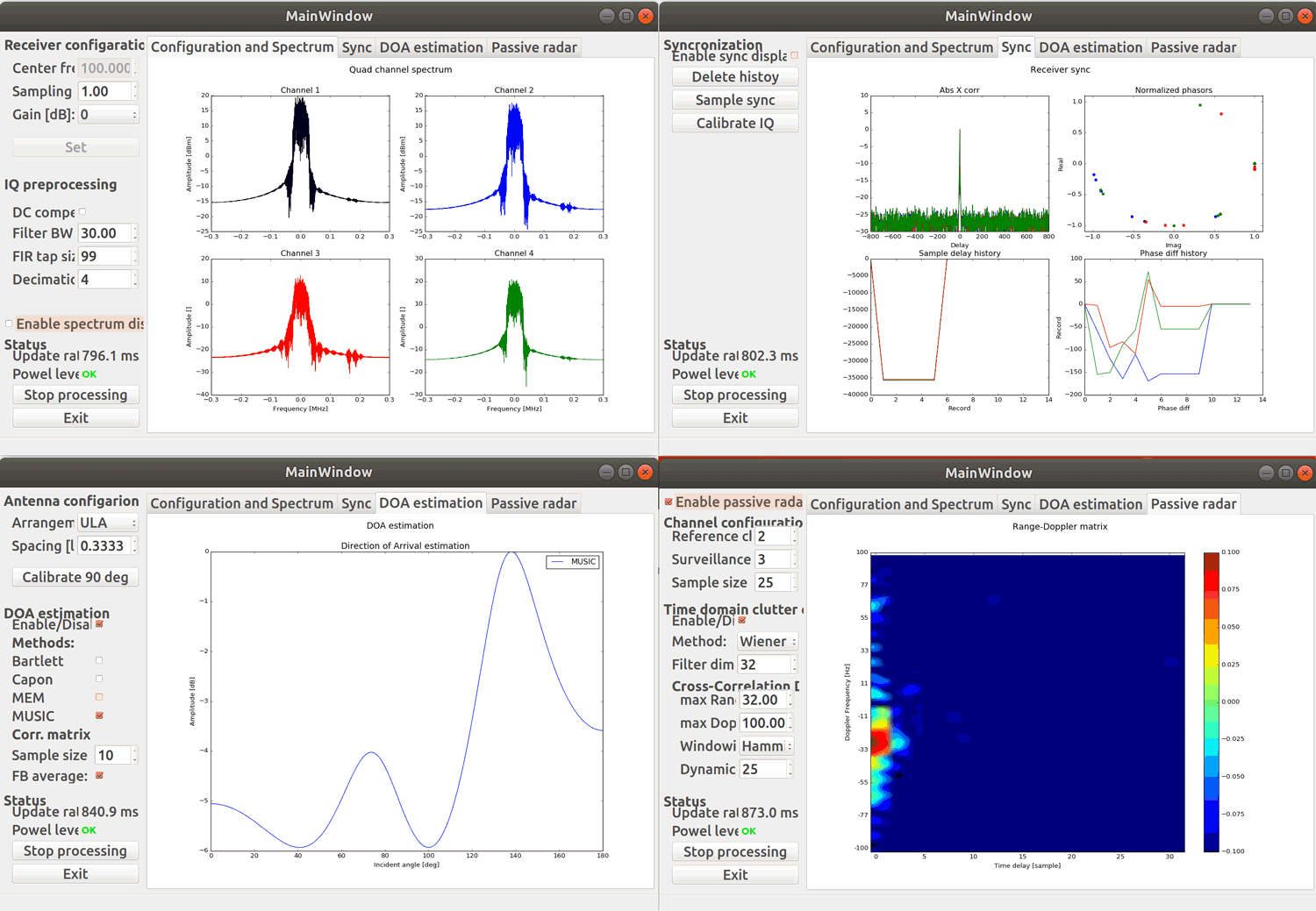
Screenshots of HydraSDR software:
Screenshots of each HydraSDR software screen
Remember, if you're interested please sign up to the HydraSDR mailing list for announcements and the chance to get in early with the cheaper first 100 units.
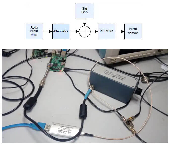
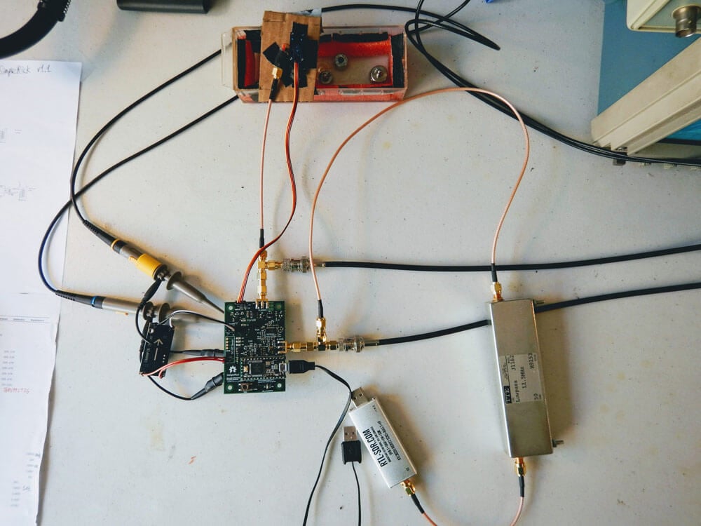
In the first test he uses RPiTX to generate a 2-FSK signal, which is then received and decoded by a RTL-SDR V3 connected to an attenuator and laptop. The Bit Error Rate (BER) is then measured while the attenuation is increased until the decoder fails. With this test he found a MDS somewhere between -115 dBm and -125 dBm, and a maximum input power of -30 dBm before clipping.
In another test he measures the RTL-SDR's ability to withstand a blocking CW signal. The results show that even with a 65 dB stronger signal just 7 kHz away, the 2-FSK modem system was able to continue working.
Finally he concludes:
So I figure for the lower HF bands this receivers performance is OK – the ADC quantisation noise isn’t likely to impact performance and the strong signal performance is good enough. An overload of -30dBm (S9+40dB) is also acceptable given the use case is remote communications where there is unlikely to be any nearby transmitters in the input filter passband.
Thanks to a RTL-SDR.COM reader for submitting a tip about radiosondy.info, a weather balloon data aggregation website made by SQ6KXY. Weather balloons carry a sensor and transmitter payload called a radiosonde. These radiosondes transmit their data to a ground station via an RF signal, which is typically at around 400 - 406 MHz in most countries. With an RTL-SDR and decoder software (related tutorial) it is possible to receive and decode their weather data, and also often their GPS location data. The location data can be used to find and collect radiosondes once they reach the ground.
SQ6KXY has created a website called radiosondy.info which aims to aggregate and make weather balloon data received by contributors public. It is similar to sites like flightradar24 which aggregate ADS-B data from aircraft. The main page allows you to view radiosondes that are currently flying, and the archive of previous flights.
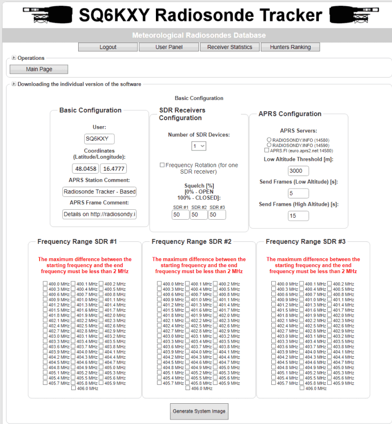
To make contributing to the site as simple as possible, SQ6KXY has created a custom image for the Raspberry Pi, which is automatically generated by the website for your particular user account, local radiosonde frequency requirements, and number of SDRs. They don't specifically mention it, but we assume that contributors are mostly using RTL-SDRs in their receivers. The custom image is available for generation after signing up.
Web tool to generate a custom Raspberry Pi Image for Radiosonde Tracking
The project is by Kazunori Miura who is the creator of the Soft66 range of RTL-SDR retrofit products. The kickstarter appears to be for the "Soft66IP", which has been around since early 2017. The main difference appears to be that now OpenWebRX is preloaded on the SDCard, and that there is a custom script running on the Orange Pi Zero which allows you to choose between OpenWebRX and HDSDR. Presumably clicking on HDSDR runs an rtl_tcp server, which can then be connected over the network.
The idea is that this system will be used together with software like OpenWebRX, which would enable the RTL-SDR and radio stream to be accessed online from anywhere in the world via an Ethernet connection. Examples of OpenWebRX receivers can be found on sdr.hu, just search for "RTL-SDR" on the page to find relevant examples.
There are several support options, with the main board (without Orange Pi Zero or RTL-SDR) starting at US$22, and US$88 for the main board including RTL-SDR, Orange Pi Zero, enclosure and SD card. The system could probably be home built for much cheaper, but there is a convenience in purchasing a ready to use system. Although if you're interested in HF and want an internet connected SDR, then you might be better off shelling out for a $299 KiwiSDR instead, which is also an OpenWebRX based SDR.
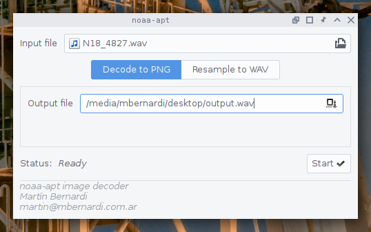
Over on GitHub user martinber has released a new NOAA APT image decoder that can run on both Linux and Windows. The decoder is called noaa-apt and takes a .WAV file of a NOAA satellite pass, and turns it into an image file. The .WAV file can be recorded in any SDR program like SDR#, HDSDR, GQRX etc. The program is programmed in Rust, and is available to install directly on Linux, or via a portable Docker image for both Windows and Linux (needs to be compiled first).
Compared to the features found in WXtoIMG the software is fairly basic, but as WXtoIMG has been abandoned it's good to see new APT decoders still being worked on. The software can also be used to simply resample the .WAV file into a sample rate required by other more featured decoders like aptdec.
NOAA weather satellites broadcast an Automatic Picture Transmission (APT) signal, which contains a live weather image of your area. With an RTL-SDR and antenna they can be received and downloaded every time one of the satellite's passes overhead. We have a tutorial on using an RTL-SDR with WXtoIMG available here.
KerberosSDR (formerly HydraSDR) is our upcoming 4-input coherent RTL-SDR. It's designed for coherent applications like RF direction finding, passive radar, beam forming and more, but can also be used as a standard 4-channel SDR for monitoring multiple frequencies. In this post we demonstrate the direction finding application running on the TinkerBoard.
Reminder: If you have any interest in KerberosSDR, please sign up to our KerberosSDR mailing list. Subscribers to this list will be the first to know when KerberosSDR goes on preorder, and the first 100 sales will receive a discounted price.
KerberosSDR Updates
This week we've managed to get the KerberosSDR demo software made by Tamás Peto functioning on a TinkerBoard. The TinkerBoard is a US$60 single board computer. It's similar to a Raspberry Pi 3, but more powerful. We've also tested the app running on the Raspberry Pi 3 and Odroid XU4. The Pi 3 is capable of running the software but it is a little slow, and the Odroid XU4 is a little faster than the TinkerBoard. In the future we hope to further optimize the code so even Raspberry Pi 3's will be smooth.
In the video below we used a circular array of four whip antennas connected to KerberosSDR. The TinkerBoard is connected to KerberosSDR and is set up to generate a WiFi hotspot, which we connect to with an Android phone and a Windows laptop. The Windows laptop connects to the TinkerBoard's desktop via VNC, and the Android phone receives an HTML/JavaScript based compass display via an Apache server running on the Tinkerboard. With this setup we can wirelessly control and view information from KerberosSDR and the TinkerBoard.
We've also tested the KerberosSDR system on a real signal, and have found it to work as expected. More demo's of that coming later.
Hackaday's Hack Chats are a weekly live community chat session where some knowledgeable guests are brought in to chat with the audience. This weeks upcoming chat on Friday is all about GNU Radio, a block based programming language that is commonly used with SDRs like the RTL-SDR. They write:
Our guests for this week’s Hack Chat will be Derek Kozel and Nate Temple, officers of the GNU Radio project. They’re also organizers of this year’s GNU Radio Conference. Also joining in on the Hack Chat will be Martin Braun, community manager, PyBOMBS maintainer, and GNU Radio Foundation officer.
GNU Radio is perhaps the most important bit of any software defined radio toolchain. This is the software that provides signal processing blocks to implement software defined radios. GNU radio is how you take a TV tuner USB dongle and pull images from satellites. You can use it for simulation, and GNU Radio is widely used by hobbyists, academics, and by people in industry.
The Hack Chat starts on Friday August 31, 2018 at noon PDT. You can leave a comment for the Hack Chat now by leaving a comment on the event page.
Over on GitHub an interesting project that involves using an ultrasound transducer and RTL-SDR to create a low cost 2D ultrasound imager has been uploaded. Ultrasound imagers transmit acoustic sound waves with a transducer at frequencies between 1 - 5 MHz, and then listens for the audio reflections from objects in the audio waves path. This technique is commonly used in the medical field for imaging inside the body without using damaging ionizing radiation like with x-rays.
The project by wlmeng11 is based on the open un0rick hardware, which is an open source ultrasound imager. wlmeng11's idea is to simplify and lower the cost of the un0rick hardware by replacing some expensive components like the FPGA and ADC with a computer and RTL-SDR. The simplified hardware is called "SimpleRick" and PCB and firmware files are also available on GitHub.
The rtl_ultrasound setup
Regarding his choice to use SDR and RTL-SDR he writes:
Why SDR?
The analog signal produced by a B-mode ultrasound (ie. 2D imaging) is essentially an Amplitude Modulated (AM) signal. The signal's envelope (ie. amplitude) corresponds to boundary information in the physical media, and the signal's carrier frequency is equal to the resonant frequency of the transducer.
Most ultrasound systems take one of two approaches for data acquistion:
Direct sampling of the ultrasound signal: This method preserves the original signal in the time domain, accomodates any transducer frequency, and offers the best flexibility for post-processing and analysis. Both amplitude and phase information can be extracted the signal, so it is useful for both B-mode and Doppler mode imaging. However, this method requires a high sample rate ADC, as well as high bandwidth and storage for the digital data.
Envelope detection with analog hardware: Perform Amplitude Demodulation (typically with a diode-based rectifier and low pass filter) to yield an envelope signal, then acquire the envelope signal at a lower sample rate. This method reduces the bandwidth and storage requirements for the digital data, but there are a number of drawbacks:
Unless the low pass filter is adjustable, this method cannot accommodate different transducer frequencies.
The non-linearity of the diode may produce harmonic distortion.
All phase information in the signal is lost, rendering it useless for Doppler mode imaging.
It has been demonstrated by Peyton et al that quadrature sampling can be used to reduce bandwidth requirements in an ultrasound imaging system.
It turns out that quadrature modulation is essential to Software Defined Radio (SDR) because any type of amplitude modulation, frequency modulation, phase modulation, or combination of these can be expressed as a special case of quadrature modulation. Therefore, many of the software and hardware techniques used in SDR can be applied to ultrasound imaging.
Why RTL-SDR?
The RTL2832U chip in the RTL-SDR takes a hybrid approach for data acquisition. It employs a high sample rate ADC (28.8 Msps), followed by a software-configurable Digital Down Converter (DDC) that produces IQ data at a lower sample rate (up to 2.56 Msps), thus reducing bandwidth and storage requirements. We can then perform envelope detection in software.
Plus, the RTL-SDR is really cheap (under $25 on Amazon in the United States)! As such, there is a lot of software support and a large community for the RTL-SDR.
With a few software tweaks, it should be possible to substitute the RTL-SDR with a more expensive SDR (eg. AirSpy HF+, LimeSDR) for use cases that require better ADC resolution and SNR.
Some of his test results are available in his August 21 writeup. His test involves a pseudo-anechoic chamber with some steel balls to reflect the ultrasound wave. The ultrasound transducer is swept through the chamber using a servo. The results so far have been successful in reliably and repeatedly resolving imaging on objects that are about 1 cm in size.
rtl_ultrasound results
If you're interested in the combination of acoustic transducers and SDRs, then this previous post shows using a piezo to detect ultrasound echolocation sounds from bats.
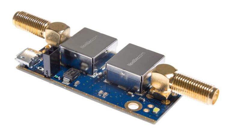
NooElec has just released their new "SAWbird" GOES LNA for sale. This is an LNA and filter combination designed to help receive GOES weather satellite images. On the PCB is a 1688 MHz SAW filter and a low noise amplifier. It can be powered with 3V - 5.5V connected directly or via bias tee. The SAWbird is currently available on Amazon and their store for US$34.95. They also have a version for Inmarsat and Iridium, so make sure you choose the correct one.
GOES 15/16/17 are geosynchronous weather satellites that beam high resolution weather images and data. In particular they send beautiful 'full disk' images which show one side of the entire earth. As GOES satellites are in a geosynchronous orbit, the satellite is in the same position in the sky all the time, so no tracking hardware is required and images can be constantly pulled down throughout the day without having to wait for a satellite to pass over.
However, compared to the more familiar and easier to receive low earth orbit satellites such as NOAA APT and Meteor M2 LRPT, geosynchronous satellites like GOES are quite a bit further away, and transmit at 1.7 GHz. So to receive the signal you'll need a dish antenna that you can accurately point, a good low noise figure LNA and possibly a filter. So setting up a receiver is a bit more difficult when compared to receivers for NOAA and Meteor satellites. The SAWbird should help however, by providing a ready to use LNA+Filter combination.
Over the past few months several testers have already received engineering samples of the SAWbird and have been successful at receiving GOES images. From the results of several experimenters, it appears to be possible to use a cheap 2.4 GHz WiFi grid antenna with some minor modifications as a GOES satellite antenna. Get one with at least a one meter long width and bend the feed as described here or here to tune reception for the 1.7 GHz GOES frequency. Pieter Noordhuis has also shown that it's possible to use an RTL-SDR to receive GOES images, so an entire GOES system can be built on a budget.
NooElec SAWbird LNA + Filter for GOES reception.GOES Full Disk Image of the Earth
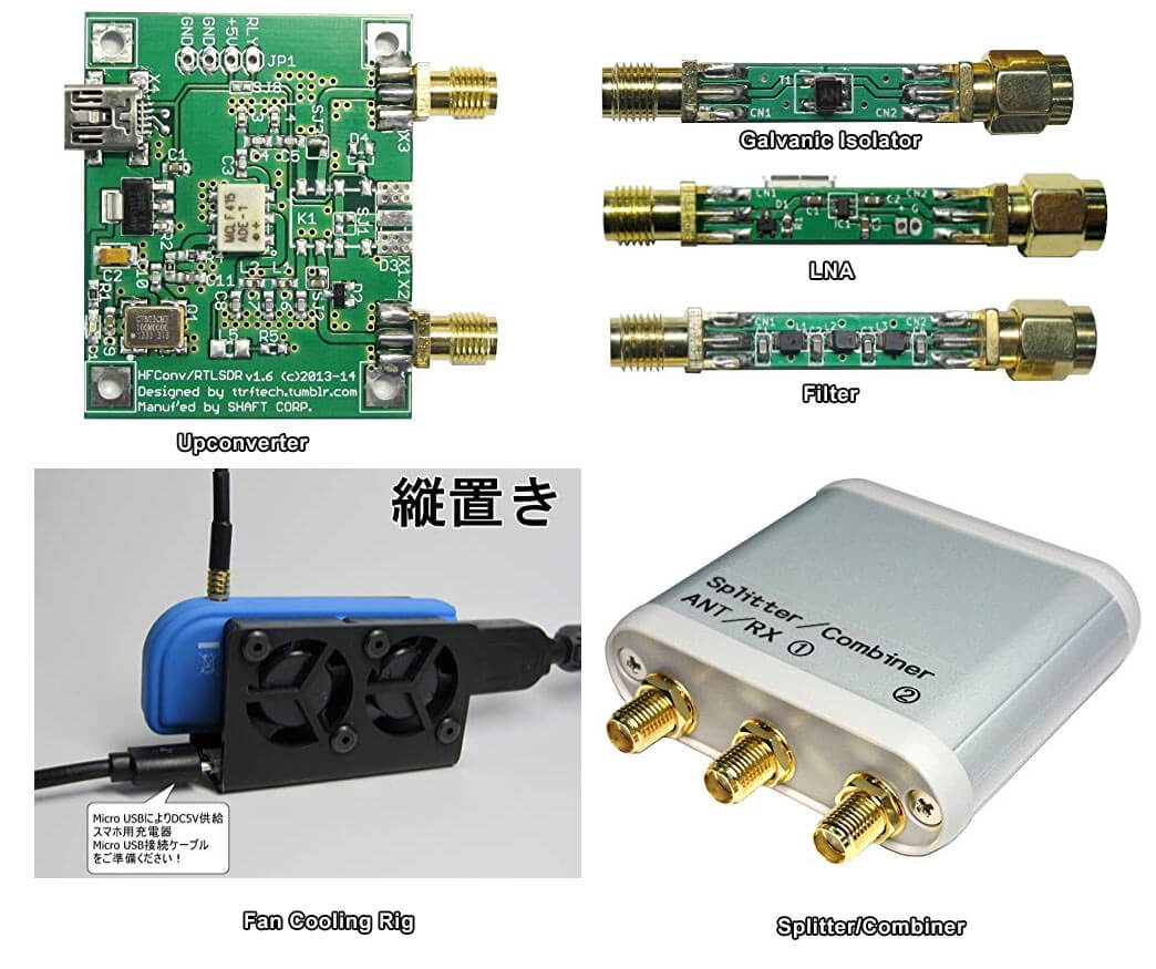
Japan has a strong RTL-SDR scene, with a few small Japanese companies and individuals (including Nobu) selling custom RTL-SDR products on their local Amazon store. Products such as upconverters, galvanic isolators, LNAs, filters, cooling products and more are available. Back in 2015 we reviewed some of these products in a post available here. Since then we've found continued use in particular with the galvanic isolator which helps reduce noise from the computer and nearby electronics at HF frequencies.
Some Custom Japanese RTL-SDR/RF Products available for International Shipping on Amazon.co.jp
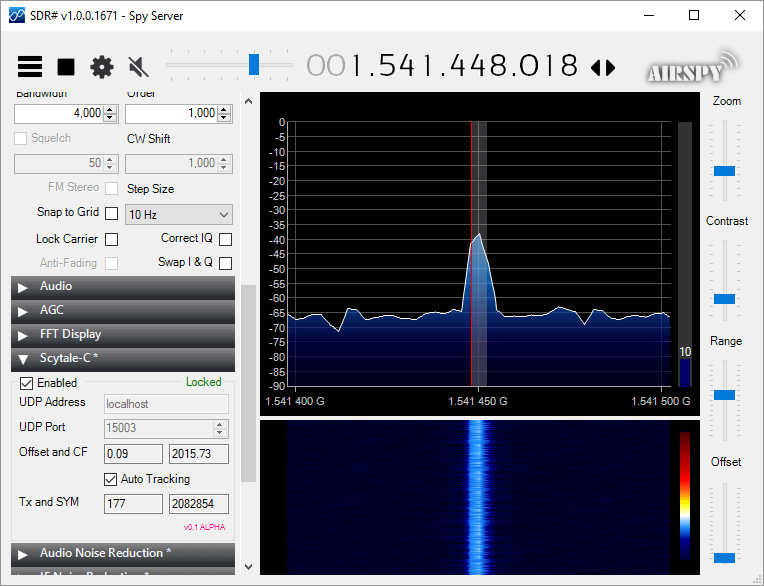
Microp11, the programmer of Scytale-C a standalone Inmarsat decoder has just released a new Inmarsat decoder SDR# plugin. The plugin is currently in the "pre-alpha" stages, so is still missing some functionality and may be buggy. However, it does appear to be functional at this point in time. It can be used with RTL-SDRs, and any other SDR# compatible SDR including units running on remote SpyServers. Microp11 writes:
I ran it with SDR# version v1.0.0.1761.
If it crashes you SDR# I apologize in advance.
The auto-tracking (default on) will alter your SDR# frequency and follow the signal’s CF. When the SNR is very low, please disable it and manually tune the SDR# to try to get the CF as close to 2000 as possible.The demodulator still has plenty ideas of its own.
Use USB mode with 4000 Hz bandwidth.
For now the interface is missing the usual scatter plots.
UDP Address and UDP Port are for sending the decoded frames to the Scytale-C UI.
Offset and CF are the difference from zero error and the CF frequency of the demodulated BPSK signal.
Tx and SYM are the transmitted over UDP frames and SYM is showing the number of demodulated symbols.
A bunch of libraries are attached as extra files. Please be gentle and accept the package as it. Will clean-up in the future.
Use in conjunction with the Scytale-C UI from the archive: “x64-UI1.6-Decoder1.4.zip” (link below)
The magic line is included in the archive: “SDRSharp.ScytaleC-1.0-alpha.zip”
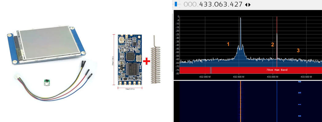
Thanks to Steve K2GOG of The Hudson Valley Digital Network (HVDN) for submitting his post on how to create a wireless display for Pi-Star. Pi-Star is a pre-built Raspberry Pi image for amateur radio users experimenting with digital voice communications like D-STAR and DMR. They write that it can be used for applications such as a "single mode hotspot running simplex providing you with access to the increasing number of Digital Voice networks, [or a] public duplex multimode repeater".
Pi-Star is compatible with serial based LED displays with built in GUIs like the Nextion. The displays are usually connected directly to the Raspberry Pi, but Steve wanted to use the display remotely. To do this he used a simple and inexpensive 70cm band HC-12 wireless serial port adapter. With the wireless adapters connected to the Pi he was able to see the pulses in SDR# via his RTL-SDR to confirm that the wireless serial signal was being sent. He then connected the second wireless adapter to the Nextion display via a few diodes to drop the voltage, and was able to get the display updating as if it was connected directly.
In the post Steve mentions that HVDN are also giving away an HC-12 and RTL-SDR to the first person to submit some progress with this idea.
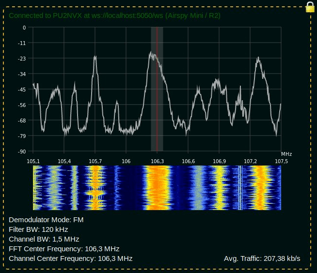
Over the last few months Lucas Teske (author of the Open Satellite Project) has been working on a piece of software called "SegDSP". The idea appears to create a web GUI based SDR receiver for SpyServer streams which can be used to create a cloud of channel demodulators, essentially segmenting the DSP computation burden over multiple computers.
SpyServer is a SDR server application that is compatible with Airspy products and RTL-SDRs. It allows you to connect to these SDRs remotely over a network or internet connection. The SDR server computer sends the radio IQ data over the network allowing you to perform processing remotely. A major advantage of SpyServer compared to other SDR server applications is that it only sends the raw IQ data for the portion of the spectrum that you're interested in which can save a lot of bandwidth.
One key application that Lucas envisions for SegDSP is using it with cloud clusters of single board computers (SBC) like the Raspberry Pi 3. The philosophy is that there will be specific roles for each SBC machine. For example you might have some SDR machines running SpyServers, some processing machines for demodulating and decoding multiple channels, and a storage machine for recording data. Then you can dynamically spawn / despawn workers when needed (for example only spawning a machine when a LEO satellite with data to decode passes over).
SegDSP development is still in the early stages, and appears to only have the web GUI set up at the moment with a few demodulators. But keep an eye on his Twitter @lucasteske for updates too. Lucas also did a talk at the last CyberSpectrum meetup. His talk can be found at 1:30:00 in the recording.
We've just released two new products in our store. The first is a low cost general purpose wideband LNA and the second is some spare RTL-SDR V3 aluminum enclosures. The wideband LNA is currently available for shipping from our Chinese warehouse and will be available on Amazon in a few days time. It costs US$17.95 including worldwide free shipping. The spare aluminum enclosure is only available from our Chinese warehouse and costs US$5.95.
The Wideband LNA is based on the Qorvo SPF4189Z LNA chip (datasheet pdf) which has the following declared specs:
Frequency range of 50 MHz to 4000 MHz
Noise figure = 0.6dB @ 900 MHz
OIP3 = 39.5 dBm @ 900 MHz
P1 Saturation = 22.7 dBm @ 1960 MHz
Gain = 18.7 dB @ 900 MHz
Compared to most of the other SPF5189Z LNAs found on eBay, our wideband LNA comes standard with a full conductive metal case, includes ESD protection on the antenna input, and is by default powered via 3 - 5V bias tee power. Our RTL-SDR Blog V3 dongles have a 4.5V bias tee built in, so they can be used to power this LNA. Direct power can be enabled simply by changing a jumper position, and removing the metal case.
This is a general purpose wideband LNA. It is useful for reducing the noise figure and thus increasing SNR, and for overcoming coax loss on all supported frequencies between 50 - 4000 MHz. However, because it is wideband you may need additional filtering if you have strong overloading signals in your area. If you're mostly interested in improving ADS-B reception, then we instead recommend our Triple Filtered ADS-B LNA which is also available at our store. The specs of the SPF5189Z are similar to that of PGA-103+ or PSA4-5043+ based LNAs. In the image slider below we compare the gain with the LNA4ALL which is a PSA4-5043+ based LNA.
Spare Aluminum Enclosure
The second product is some spare RTL-SDR Blog V3 aluminum enclosure. A few readers of this blog contacted us as they found RTL-SDR V3 enclosures to be a good fit (after being cut down to size) for home made filters, other LNAs and for FlightAware dongles. Our spare enclosures come with two SMA side panels, and one USB side panel. There is only limited stock of this product at the moment. Note that we're not including a thermal pad, since FlightAware dongles do not require additional cooling since they operate at 1.09 GHz. Additional cooling via thermal pad is only needed for stable operation when using RTL-SDRs above ~1.5 GHz.
KerberosSDR is our upcoming low cost 4-tuner coherent RTL-SDR. With four antenna inputs it can be used as a standard array of four individual RTL-SDRs, or in coherent applications such as direction finding, passive radar and beam forming. More information can be found on the KerberosSDR main post. Please remember to sign up to our KerberosSDR mailing list on the main post or at the end of this post, as subscribers will receive a discount coupon valid for the first 100 pre-order sales. The list also helps us determine interest levels and how many units to produce.
In this post we'll show an experiment that we performed which was to pinpoint the location of a transmitter using KerberosSDR's coherent direction finding capabilities. RF direction finding is the art of using equipment to determine the location of a transmitting signal. The simplest way is by using a directional antenna like a Yagi to try and determine the bearing based on signal strength. Another method is using a pseudo-doppler or coherent array of antennas to determine a bearing based on phase information.
For the test we tuned the KerberosSDR RTL-SDRs to listen to a signal at 858 MHz and then drove to multiple locations to take direction readings. The antennas were set up as a linear array of four dipole antennas mounted on the windshield of a car. To save space, the dipoles were spaced at approximately a 1/3 the frequency wavelength, but we note that optimal spacing is at half a wavelength. The four dipole antennas were connected to KerberosSDR, with a laptop running the direction finding demo software.
Low cost direction finding array mounted to vehicle windshield.
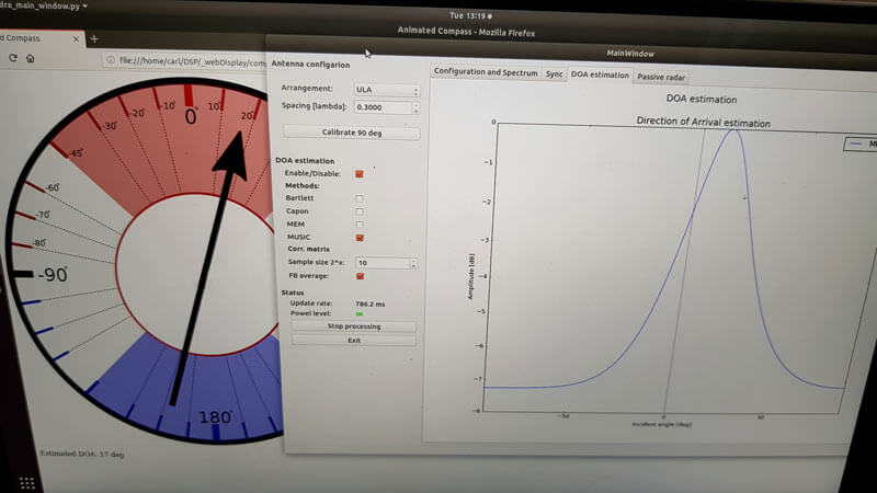
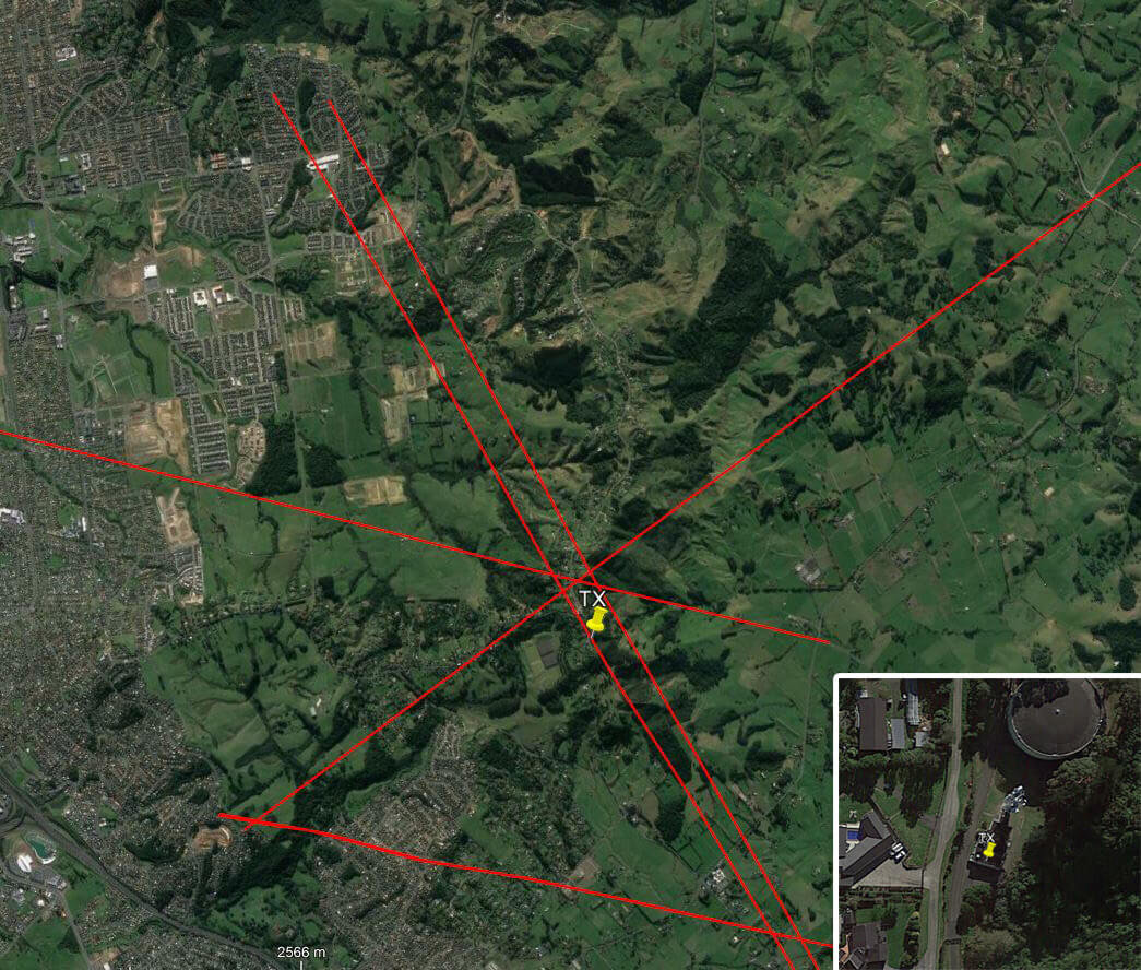
Our open source demo software (to be released later when KerberosSDR ships) developed by Tamás Peto gives us a graph and compass display that shows the measured bearing towards the transmitter location. The measured bearing is relative to the antenna array, so we simply convert it by taking the difference between the car's bearing (determined approximately via road direction and landmarks in Google Earth) and the measured bearing. This hopefully results in a line crossing near to the transmitter. Multiple readings taken at different locations will end up intersecting, and where the intersection occurs is near to where the transmitter should be.
KerberoSDR SDR Directing Finding DOA Reading
In the image below you can see the five bearing measurements that we made with KerberosSDR. Four lines converge to the vicinity of the transmitter, and one diverges. The divergent reading can be explained by multipath. In that location the direct path to the transmitter was blocked by a large house and trees, so it probably detected the signal as coming in from the direction of a reflection. But regardless with four good readings it was possible to pinpoint the transmitting tower to within 400 meters.
In the future we hope to be able to automate this process by using GPS and/or e-compass data to automatically draw bearings on a map as the car moves around. The readings could also be combined with signal strength heatmap data for improved accuracy.
This sort of capability could be useful for finding the transmit location of a mystery signal, locating a lost beacon, locating pirate or interfering transmitters, determining a source of noise, for use during fox hunts and more.
KerberosSDR pinpointing a transmitters locationKerberosSDR Prototype
On The Thought Emporium YouTube channel a new video has been uploaded showing the full disk images of the earth that they've been able to receive from GOES geosynchronous weather satellites. Over the past couple of years GOES satellite reception has become much easier for hobbyists to achieve with the release of the NooElec SAWbird LNA+Filter, information on how to use a cheap 2.4 GHz WiFi grid antenna for reception and the release of free open source decoder software. It was also shown that an RTL-SDR dongle is sufficient for receiving these images as well. With all these new developments it is now possible to build a GOES receiving station for under $100.
The Thought Emporium video blurb reads:
In the fall of 2016 I saw my first rocket launch and little did I know that the satellite on that rocket would come to shape and fill my thoughts for many years. We're no strangers to getting data out of space on this channel, but GOES-16 is special, and not just because I was there when it left earth. Unlike the satellites we looked at in the past, GOES is in geostationary orbit and has an amazing suite of cameras and sensors on board. While it's a bit harder to receive data from GOES the extra effort is absolutely worth it, especially because it can see then entire globe all at once and send out those images in stunning high resolution. And it even comes with the added bonus of rebroadcast data from other satellites giving us a view of the opposite side of the planet as well.
In this video we go through the hardware and software needed to receive these gorgeous images and what is contained in the signals we receive.
How to Receive Beautiful Images of the Earth Directly From Space | GOES-15,16,17 and Himawari 8 HRIT
KerberosSDR is our upcoming low cost 4-tuner coherent RTL-SDR. With four antenna inputs it can be used as a standard array of four individual RTL-SDRs, or in coherent applications such as direction finding, passive radar and beam forming. More information can be found on the KerberosSDR main post. Please remember to sign up to our KerberosSDR mailing list on the main post or at the end of this post, as subscribers will receive a discount coupon valid for the first 100 pre-order sales. The list also helps us determine interest levels and how many units to produce.
In this post we'll show KereberosSDR being used as a passive traffic radar. Passive radar works by using an already existing transmitter such as a FM, DAB, TV or GSM and listening to the reflections of those signals created by moving objects like aircraft, boats and cars. A simple passive radar consists of two directional antennas. One antenna points at the 'reference' transmitter (the transmitting tower), and the other towards the 'surveillance' area that you want to monitor. The result is a speed vs distance plot that shows all the moving objects.
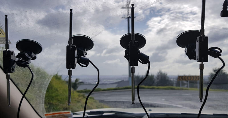
For this test we parked our car to the side of a highway and pointed a cheap DVB-T Yagi antenna towards a DVB-T transmission tower, and another cheap Yagi down the road. The video shown below displays the results captured over a 5 minute period. The blips on the top half of the display indicate vehicles closing on our location (positive doppler shift), and the blips on the bottom half indicate objects moving away (negative doppler shift).
Highway Passive Radar Traffic Monitor with DVB-T and KerberosSDR a 4x Coherent RTL-SDR
DVB-T Antennas In Car
The resolution of each individual vehicle is not great, but it is sufficient to see the overall speed of the highway and could be used to determine if a road is experiencing traffic slowdowns or not. When larger vehicles pass by it is also obvious on the display by the brighter blip that they show. The display also shows us that the highway direction coming towards us is much busier than the direction moving away.
In the future we'll be working on optimizing the code so that the display updates much faster and smoother. It may also be possible in the future to use the third and fourth tuners to obtain even greater object resolution.
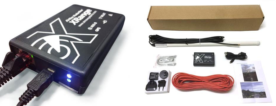
The team at radarbox24.com recently wrote in and wanted to share some new developments including news about their recently released RadarBox XRange receiver, which is an RTL-SDR based ADS-B receiver. Radarbox24 are an ADS-B aggregation flight tracking website, similar to sites like flightaware.com and flightradar24.com.
The RadarBox XRange receiver costs $649.95 USD and is available on their store. The box appears to include a full computing unit as well as a custom RTL-SDR receiver, and a built in filter and LNA as well. It is sold as a set that includes receiver, power supply, antenna and cabling. Compared to setting up an ADS-B receiver on your own by purchasing an RTL-SDR, ADS-B LNA/Filter, Antenna and Raspberry Pi separately, the XRange is well over three times more expensive. But it may have some value as an easy to set up and ready to go ADS-B receive system. They write:
1- We have release the brand new RadarBox app for iOS and Android where data sharers are able to see what what their own stations receive using the MyStation feature.
2- We've released the brand new RadarBox XRange receiver, RTL SDR based whcih is being sold and placed all over the world to increase network coverage.
3- Our RadarBox24.com flight tracking portal reached 3 millions viewers per month and, together with our apps, is growing really fast by providing an easy way for Raspberry Pi owners or users with our XRange and Micro RadarBox receivers to share flight data with us and benefit from a free Business account.
More information: - Link to our Store where users can buy the XRange receiver and accessories below: https://www.radarbox24.com/store
- Link for users to install our software on their Raspberry Pi receivers and start sharing data with us (we get up to 5 new added units added to our network daily): https://www.radarbox24.com/raspberry-pi