[@Lugigi Cruz] has announced on twitter that his latest PiSDR image now includes full PlutoSDR support. PiSDR is a pre-built Raspberry Pi distribution that supports several SDRs including the RTL-SDR. It comes with many applications and libraries ready for you to use some of which include GQRX and GNURadio Companion. PiSDR is available on [GitHub] and just needs to be burned to an SD card to be used. The PlutoSDR is a low cost (typically priced anywhere between $99 – $149 depending on sales) RX/TX capable SDR with up to 56 MHz of bandwidth and a 70 MHz to 6 GHz frequency range.
With this update support for the PlutoSDR has been added. This should allow for a host of new interesting uses for the image as it includes SDRAngel, an SDR application that works with transmit capable SDRs. While I’ve not yet tested the image myself, this should in theory mean that the PiSDR image could be used with a transmit capable SDR like a PlutoSDR or Lime/Mini SDR to both transmit and receive anything from DATV to voice and more.
Below you can see the image running the Raspbian desktop with the SDRAngel software connected to the PlutoSDR. Those with a keen eye may also see the LimeSDR mini laying on the desk s well. The concept of SDR on a small microcomputer such as the Raspberry Pi isn’t a new one, but the existence of this distribution makes it much easier for people to jump in and start using it without having to configure and install software from scratch which can sometimes be a daunting task.
Over on YouTube Nick Black has uploaded a video where he does a good introduction to software defined radio (SDR), SDR history, how SDR works, various SDR concepts like sampling and bandwidth, different SDR hardware, the SDR Linux stack and reverse engineering wireless signals.
The information is presented fast and densely, so it may be a bit hard to follow for newbies, but if you already have some experience with SDR it may be a good video that helps tie everything together and fill in some gaps. Nick also has a Wiki where he's documented some of what is said in the video.
Thank you to Happysat for submitting the following information about the updated LRPT decoder for Meteor M-N2-2. He has also provided a link to his very useful Meteor Satellite reception tutorial.
Today the official LRPT-Decoder V42 ready for release :)
Before we did use a older internal debug version from 2014, because this one was still in development.
This version 42 of LRPTDecoder will work with both Meteor M-N2 and Meteor M-N2-2.
Example ini configuration files for other modes are attached in the archive.
Every device that transmits radio waves has a unique and identifiable RF fingerprint which occurs due to the very slightly variations in the hardware manufacturing process. This means that devices using identical transmitters of the same make and model can still be differentiated from one another.
Nihal Pasham has been using this knowledge as a way to securely identify IoT sensors and other RF devices like car keyfobs. The idea is that these unique RF fingerprints are immune to authentication spoofing which could be used to create a fake transmitter with fake data. He suggests that RF fingerprinting could be used as an additional authentication check for low cost IoT devices with only basic security.
In order to recognize the minute differences in the RF fingerprints of different devices Nihal notes that a good pattern detection algorithm is required, and that a deep learning neural network fits the bill. Using neural network software Tensorflow, and an RTL-SDR for signal acquisition, he was able to train a proof of concept neural model that was able to classify two test transmitters with 97% accuracy.
Training a Deep Learning Neural Network with an RTL-SDR for RF Fingerprinting
In the past we've seen similar experiments by Oona Räisänen who used an RTL-SDR to fingerprint several hand held radios heard on the air via small variances in the power and frequencies of each radio's CTCSS tone. Using simple clustering techniques she was able to determine exactly who was transmitting based upon the unique CTCSS.
With so many independent people receiving weather satellite images from the NOAA satellites daily, an interesting collaborative task is to stitch these images together to create a wide area composite image. Fortunately the WXtoIMG software already has stitching as a feature.
NOAA Weather Satellite Composite created with images from Jeff Kelly (New Jersey, US), Mike Kimzey (Philadelphia, US), David Kunz (San Francisco, US), Cornelius Danielsen (Norway), Alan Hinton (UK), Michael Sørensen (Denmark), and Hans-Juergen Luethje (Germany).
Weather Satellite Failure Updates
We also wanted to provide a brief update on some weather satellites that we RTL-SDR users often receive.
NOAA 15: About two weeks ago NOAA 15 failed and was producing glitched images. However after a few days it came right again, only to have failed again at the end of last month. It appears that the camera scanning motor is getting stuck due to being low on lubricant as the satellite is now well past it's intended life cycle at 11 years old. If you're interested, some info on how the camera on these satellites works can be found here. There is currently no plan for a fix, the only hope is to wait and see if the motor unsticks.
Meteor M2-1: Meteor M2-1 has also recently suffered problems yet again with it's orientation control, and we're regularly seeing off-axis or distorted images that show the curvature of the earth. Over the weekend it was turned off, and should be reset this week. This problem seems to occur and be fixed often, so hopefully it will be back online soon.
Meteor M2-2: The recently launched Meteor M2-2 is functional, but it is still in the testing phase, so is sometimes being turned off. Do not be alarmed if no signal is received sometimes.
GOES-17: GOES-17 is reported to be experiencing problems with it's infrared camera due to a blocked heatpipe, however it appears that they are able to work around this issue and obtain 97% uptime.
The process to install an RTL-SDR dongle on Windows involves the simple step of running Zadig and installing the generic WinUSB drivers to the RTL-SDR, which shows up as "Bulk-In, Interface (Interface 0)" in Zadig.
However we find that people sometimes accidentally use Zadig to install WinUSB to "Bulk-In, Interface (Interface 1)" by mistake. Installing WinUSB to this interface can break your installation, and it can cause the RTL-SDR to display a "usb_open error -12" on command line software, and can cause problems connecting to the device on GUI software like SDR#.
Over on YouTube Corrosive from the SignalsEverywhere YouTube channel uploaded a very useful video that shows how to fix this problem.
Over on YouTube Corrosive from the SignalsEverywhere channel has uploaded a new video showing us how you can make a DIY upconverter using a HackRF as a signal source and a cheap $10 RF Mixer. An upconverter converts lower frequencies into higher frequencies. For example, an upconverter is commonly used to convert HF signals into VHF, so that VHF/UHF only SDRs can receive HF.
In the video he uses the HackRF as a local oscillator source, a cheap RF mixer on a breakout board, and an Airspy as the receiver. In most circumstances if you needed and upconverter you'd just purchase one like the Ham-it-up, or the Spyverter for ~$40. However the interesting advantage of using a versatile signal generator like the HackRF is that it results in an upconverter that can upconvert HF to almost any frequency. Even without any filtering (which is recommended to remove signal images), Corrosive fings that he has excellent HF reception.
This video is an excellent way to learn about how upconverters work.
HackRF and RF Mixer = DIY RTL SDR Up-converter | Basics of the Passive ADE Mixer
We have just released an updated version of the KerberosSDR Android direction finding app. If you didn't already know KerberosSDR is our experimental 4x Coherent RTL-SDR product. With it, coherent applications like radio direction finding (RDF) and passive radar are possible. Together with the KerberosSDR direction finding Android app it is possible to visualize the direction finding data produced by a KerberosSDR running on a Pi3/Tinkerboard.
The KerberosSDR hardware is currently in preorder status on Indiegogo for the second production batch, and we expect it to be ready to ship out this month. If you preorder then you'll be able to purchase a KerberosSDR at a reduced price of USD$130. After shipping for batch two begins the price will rise to USD$150.
The new version of the KerberosSDR Android app adds the following features:
Heatmap Grid Plotting
Precise TX location pinpointing when enough data points are gathered
Turn by turn navigation to the RDF bearing direction / TX location
Bearing moving average smoothing
To understand what these features are, we've released two demo videos showing them in action. In the first video we use the new features to find an 858 MHz TETRA transmitter, and in the second video we find a 415 MHz DMR transmitter. The first video explains the new features so we recommend watching that first.
KerberosSDR Radio Direction Finding: Heatmap + Auto Navigation to Transmitter Location Demo 1
KerberosSDR Radio Direction Finding: Heatmap + Auto Navigation to Transmitter Location Demo 2
Over on YouTube user [Radio Electronics] has uploaded a useful video showing how to install your own personal SDRplay or RTL-SDR based WebSDR for QO-100 (aka Es'Hail-2) reception. Es'Hail-2 is the first geostationary satellite with amateur radio transponders on board, and is positioned at 25.5°E which covers Africa, Europe, the Middle East, India, eastern Brazil and the west half of Russia/Asia.
The idea behind a WebSDR is to run your RTL-SDR QO-100 receiver on a remote Raspberry Pi (perhaps mounted close to the antenna on your roof etc). The Pi runs custom WebSDR software that has been created from scratch by [Radio Electronics] specifically for monitoring Es'Hail-2. Then you can access your QO-100 receiver from any device on your network that has a web browser (computer/phone/tablet etc). The interface of his WebSDR appears to be quite slick, which multiple QO-100 specific options and labels.
Quite a lot of work must have gone into this software which looks to be of high quality, so it is definitely worth checking out if you are interested in QO-100/Es'Hail-2 monitoring.
Es'Hail-2 QO-100 WebSDR
In the first video he first talks about various methods for downconverting the 10489.550 MHz QO-100 CW signal into a range receivable by the RTL-SDR or SDRplay. He then goes on to show the exact steps to install and run his WebSDR software on a Raspberry Pi 3.
In the second video he goes on to demonstrate the web browser interface highlighting the QO-100 specific features that he has implemented such as being able to compensate for any LNB frequency drift via a feature that can lock to the QO-100 PSK beacon.
NooElec have recently released a new LNA + filter combo called the "SAWbird+ H1 Barebones" which significantly lowers the entry bar for new amateur radio astronomers. It's designed to be used with RTL-SDR or other SDRs for radio astronomy, and in particular reception of the Hydrogen line.
The filter is centered at 1.42 GHz with a 70 MHz bandpass region. The LNA has a minimum gain of 40dB. For hydrogen line observations it is important that the LNA have very low noise figure, and this LNA fits the bill with a ~0.5dB to ~0.6dB noise figure. An additional feature on the PCB is an RF switch that is electrically controlled via expansion headers. This switch allows you to switch out the LNA for a 50 Ohm reference which is useful for calibration in more serious radio astronomy work.
This LNA draws 120mA of current meaning that it will work with the RTL-SDR V3 and Airspy's bias tee, but probably not with the SDRplay's bias tee which is limited to 100mA and seems to trip a fuse at higher current draws. For an SDRplay you could use external power instead, although you will need an additional DC blocking cap to prevent power from entering the SDR and destroying the ESD diodes.
If you don't know what the Hydrogen line is, we'll explain it here. Hydrogen atoms randomly emit photons at a wavelength of 21cm (1420.4058 MHz). Normally a single hydrogen atom will only very rarely emit a photon, but space and the galaxy is filled with many hydrogen atoms so the average effect is an observable RF power spike at 1420.4058 MHz. By pointing a radio telescope at the night sky and integrating the RF power over time, a power spike indicating the hydrogen line can be observed in a frequency spectrum plot. This can be used for some interesting experiments, for example you could measure the size and shape of our galaxy. Thicker areas of the galaxy will have more hydrogen and thus a larger spike. You can also measure the rotational speed of our galaxy by noting the frequency doppler shift.
Although this LNA lowers the entry bar, in order to receive the Hydrogen line with the SAWBird+ H1 you will still need a ~1m+ satellite dish and a feed tuned to 1.42 GHz or high gain Yagi, horn or helical antenna. Antennas and feeds like this are not yet available off the shelf, but if you search our blog for "hydrogen line" you'll see many project examples.
The NooElec SAWBird+ H1. For Hydrogen Line Observations.
Why use this app? It makes it easy to slog through lots of recording files, looking for interesting signals. Load a file, and a waterfall for the entire file is created. You can scroll around, and if you see anything that looks interesting, you can drag select it, and then demodulate it. You can even save the demodulated audio as a WAVE file, that you can listen to later, send to someone else, or play into your digital decoding software, if it is an RTTY, SSTV, etc. transmission.
Support for other SDR recording file formats is possible, you'll need to work with me by providing sample files and details on the format. This program is presently for macOS only. Support for Windows may happen... stay tuned!
mySdrPlayback now supports SDR# and SDRUno IQ Files.
The SignalsEverywhere YouTube channel is quickly growing in size, and has recently passed the 10,000 subscriber milestone. If you weren't aware, Corrosive (aka KR0SIV aka Harold) who runs the channel has been consistently putting out high quality videos related to the software defined radio hobby. He's also started a podcast which also covers some interesting topics.
Some Recent SignalsEverywhere YouTube Videos
To celebrate hitting the 10,000 subscriber mark, Harold is planning an interactive 6 hour+ YouTube live stream which will begin on Saturday August 10 12PM EST time (11 hours from the time of this post). If you want to be automatically reminded of the stream, go to the live stream place holder, and click on set reminder.
The stream will be interactive as he is planning on setting up several SpyServer's that will be running across the HF, VHF, UHF and L-Bands. This will allow the audience to use SDR# to connect to his SDRs that are being used on the stream, allowing people to follow along with what Harold is doing on the stream, and ask questions about what they are seeing.
We're also helping to sponsor his stream and will be donating 5x RTL-SDR dongle + antenna kits, 5x RTL-SDR dongles, 1x Radarbox bundle, as well as one KerberosSDR to any giveaways that he plans on doing throughout the stream.
We really like Harolds work on YouTube, and if you are a fan of the content on our RTL-SDR.COM blog, then you really should be subscribed to his channel too.
Interactive SDR Live Stream | 10K Subscriber Celebration and Giveaway!
You may recall that a few years ago we released a tutorial on how to set up and use [SDRTrunk]. Fast forward a few years and the software has seen numerous changes. This application was designed primarily for tracking trunking radio systems but also has the ability to decode things like MDC-1200, LoJack and more.
The software is compatible with many Software Defined Radios such as our RTL-SDR v3, HackRF and the Airspy. Some of the newer improvements include a bundled copy of java so that an installation of java is not required on the host computer, as well as decoding improvements for P25 among other digital voice modes. You can find a full list of improvements along with the latest release on [GitHub]
The biggest feature many have been waiting for is the ability to import talk groups for their radio system into the application from radio reference. While this has not yet been implemented, user [Twilliamson3] has created a [web application] that will convert table data from radio reference into a format that is supported by SDRTrunk.
ADSB Flight Tracker is an Android App that allows you to display ADS-B flight data in either 2D or 3D. It works either with data shared from others over the internet via aggregation sites like adsbexchange.com, or via your own home ADS-B receiver data coming from an RTL-SDR and dump1090 server on your home network. You can also directly connect to an RTL-SDR that is running on your phone and this will allow you to get data faster with less lag. Using data shared by others from the internet could have a delay of a few seconds.
In order to keep using the 3D and RTL-SDR features you'll need to unlock them for a small in-app purchase of $2 for each feature. Initially you get about 30 minutes trial time however.
2D and 3D Screenshots from ADS-B Flight Tracker
Some interesting 3D videos were also recently posted to the apps Twitter page @ADSBFlightTrkr.
GNU Radio Days 2019 was a workshop held back in June. Within the last week recordings of the talks have been uploaded to YouTube by the Software Defined Radio Academy channel. The talks cover a wide range of cutting edge SDR research topics and projects. Many of the presenters have also made use of RTL-SDR dongles, as well as other higher end SDRs in their research.
All the talks are combined into two 3 hour long videos from the morning and day sessions from day one. Day two also has two videos that consist of recordings from the tutorial sessions which make use of the PlutoSDR. Finally there is also the keynote speech from Marcus Müller where he dives into the internal workings of GNU Radio.
Below we list the talks with timestamps for the YouTube video. Short text abstracts for each of the talks can also be found in the conference book. We note that not all the abstracts appear to have been presented in the videos, so it may be worth checking out the book for missed talks about passive radar, a 60 GHz link, embedded GNU Radio on a PlutoSDR, an SDR 802.11 infrared transmission system, PHY-MAC layer prototyping in dense IoT networks and hacking the DSMx Drone RC protocol.
Day One: Morning Session
00:19:00- Array signal processing optimization in GNU Radio for tracking and receiving applications, Bieber E [et al.]
Among other missions the French German research Institute of Saint-Louis (ISL) works on array signal processing for secured communications between high speed projectiles and allied base stations. Within that framework, a projectile tracking receiving station based on commercial Software-Defined Radios (SDR) was developed using four channels to steer an antenna array and recombine the received signals, hence improving the gain of the receiving station. A transmitter embedded in the projectile sent data to the developed receiving station at a 2 Mbits/s. In order to decode and process in real time the data received by the four channel antenna array, a high sampling rate was required. As this highly resource consuming application resulted in sample overflows that is, in periodic losses of data between the SDR and the computer, an optimization of our algorithms computed on GNU Radio and the communication between our blocks proved to be necessary. This paper intends to provide feedback on our optimization work. Some of the main problems we encountered and the solutions we propose to solve them are briefly exposed and will be further detailed in our oral presentation
00:43:00 - SatNOGS: Towards a Modern, Crowd Sourced and Open Network of Ground Stations, Julien Nicolas
Over the last years the launching cost of a payload in space has been significantly reduced and this trend is expected to continue, as the interest for space applications is increasing. The reduced launch cost and the advancements in technology, gave the opportunity to small satellites to revolutionize access to space.
The majority of the small satellites missions are targeting the Low Earth Orbit (LEO). Due to the nature of this particular orbit, communication with a satellite is possible only for a few minutes per day for a given location. This raises the need for multiple ground stations in several geographic locations. Although such an infrastructure is possible, most of the times it is both complicated and expensive for research or educational entities to obtain. Given the fact that each ground station exhibits a small per day utilization for a specific satellite, the idle time can be used for reception of other missions. SatNOGS is an open source software and open hardware project that addresses this problem by interconnecting all participating ground stations, offering their idle time to other users of the SatNOGS network.
1:10:40 - Using GNU Radio to do signal acquisition and analysis with Scopy
1:37:30 - Embedded and Connected Receiver System for nano-satellite in Low Earth Orbit (LEO), Spies Francois [et al.]
The objective of this work is to design a set of satellite signal reception, embedded, connected and low power consumption. This set must be simple to implement with the ambition of being widely deployed on a global scale to provide complete and continuous coverage so that each satellite transmission can be received at any time without loss. The altitude of the satellite orbit must allow the planet to be covered with less than a hundred reception stations on earth. The stations will be located mainly in universities with an eduroam connection to facilitate the transmission of information on a server.
1:59:40 - KiwiSDR as a new GNURadio source, Mayer Christoph
By now, >300 world-wide distributed KiwiSDRs are online. After introducing the KiwiSDR, an implementation of a GNURadio websocket client for the KiwiSDR. As an example on how to use the GNURadio KiwiSDR client, the coherent combination of KiwiSDR IQ streams, and decoders implemented in GNURadio for digital HF modes using the KiwiSDR client are shown.
2:30:20 - Using GNU Radio Companion to improve student understanding of signal processing theory through VHF Omni-Directional Range (VOR) signal demodulation, Blais Antoine [et al.]
The École Nationale de l'Aviation Civile (ENAC), the French Civil Aviation University, proposes a graduate engineer program with, among three others, a major, in Aeronautical and Space Telecommunications (SAT). This major is characterized by advanced theoretical courses in signal theory, signal processing, digital communications and navigation in particular. Some practicals are given to help the students understanding specific points in these courses. However, this scattered approach does not provide any hindsight on the interest and the usefulness of these courses, either independently nor together. This is the reason why these practicals are completed by a long project which proposes, as a global case of application, to demodulate a VHF Omni-Directional Range (VOR) signal. This paper details this long project, from its pedagogical approach to some interesting points of its implementation.
GNURadio Days 2019, First Day Morning Session
Day One: Afternoon Session
00:00:30 - VLBI with GNU Radio, RFNoC and White Rabbit, Boven Paul
00:35:25 - Fully Digital Electronics for Fiber-Link Frequency Transfer Implemented on Red Pitaya, Cardenas Olaya Andrea Carolina [et al.]
This paper presents a digital instrumentation for frequency transfer on optical fiber links. The proposed system detects the phase and amplitude of the beatnotes at the two ends of the fiber for (actively or passively) compensating by the phase noise and the polarization rotation. The implementation is performed on Red Pitaya, an open source platform that integrates fast Analog-to-Digital and Digitalto-Analog converters with a Zynq System-on-Chip. The system features a detection bandwidth of 10 MHz, compatible with thousand kilometers links, that can be finely tuned for reaching an adequate Signal-to-Noise Ratio minimizing the generation of cycle slips.
00:56:30 - Frequency locking a laser on a spectral hole pattern with a multi-channel heterodyne method using SDR and GnuRadio, Galland N [et al.]
High precision spectroscopic probing of a narrow spectral hole pattern imprinted in the inhomogeneously broadened absorption spectrum of Eu3+ : Y2SiO5 crystal can be used to stabilize a laser frequency. A multi-hole pattern can be burn and all the holes can be probed simultaneously using a multiple frequency signal. The dispersion induced dephasing acquired by the light through the crystal is measured to derive an error signal suitable to lock the laser frequency to the spectral hole pattern. An Ettus USRP X310 driven by a python program based on GNU Radio is used for both generating the multiple frequency signal and to compute the correction applied to the laser frequency.
1:23:50 - A LoRaWAN Security Assessment Test Bench, Claverie Tristan [et al.]
LoRaWAN is a recent protocol and despite having been already studied from a security perspective, several attacks have not been reproduced in practice mostly due to a lack of details regarding the test benches used. After presenting previous work on the LoRaWAN protocol and the various platforms described, we present an environment based on hardware, software and SDR to study the radio layer of the protocol. The efficiency of this architecture is demonstrated by reproducing theoretical attacks on LoRaWAN 1.0
1:54:05 - GNU Radio implementation for Multiuser Multi-Armed Bandit learning algorithms in IoT networks, Manco Julio [et al.]
Novel access schemes based on multi-armed bandit (MAB) learning approaches has been proposed to support the increasing number of devices in IoT networks. In the present work, a GNU radio framework is implemented to recreate an IoT network where IoT devices embedding MAB algorithms are able to learn the availability of the channel for their packet transmissions to the gateway. It allows to incorporate several IoT users recognized by an identifier (ID), and provides a gateway to handle a large number of IDs as well as the packet collisions among IoT devices. The experimental results show that the introduction of learning mechanism in access schemes can improve the performance of the network.
2:13:33 - Phase noise & digital noise: what is it and why it is important for groundbreaking RF-applications., Bourgeois Pierre-Yves
For more than a decade, digital electronics has a massive impact on about every research field offering flexibility, robustness and reconfigurability.
GNURadio Days 2019, First Day Afternoon Session
Marcus Müller Keynote: The GNURadio scheduler and internals
GNURadio Days 2019, Marcus Müller Keynote: The GNURadio scheduler and internals
Day Two: Tutorial Session One
00:00:50 - Exploring the Radio-Frequency Spectrum
02:11:00 - GNU Radio Internals (Writing Out of Tree Blocks for GNU Radio)
GNURadio Days 2019, Second Day,Tutorials, Morning Session
Day Two: Tutorial Session Two
00:50:00 - Brief Intro to Software Defined Radio from ADI
01:23:00 - Hands-on Workshop: Introduction to ADALM-PLUTO and IIO
1:40:30- Hacking Nordic proprietary protocol with GNU Radio
GNURadio Days 2019, Second Day,Tutorials, Afternoon Session
If you've been following our blog, or have your own RTL-SDR based weather satellite station, then you'll know that the NOAA-15 APT satellite has been experiencing issues lately. There appear to be problems with it's camera scan motor resulting from it running low on lubrication. This is fully understandable as the satellite is 21 years old and well past it's expected life span. The satellite appears to be working some days, and producing garbage image other days.
When NOAA-15 fails for good, don't feel too bad as we still have NOAA-18 and NOAA-19, the Russian Meteor M2, and Meteor M2-2 satellites, and the GOES satellites, all of which can be received by an RTL-SDR. Several new weather satellites are also planned for 2020 and onwards.
A few days ago we posted about [dj0abr / Radio Electronics'] WebSDR software for QO-100. Having looked through his GitHub we've seen that he also has an a similar browser based server tool called WebWSPR for WSPR decoding and visualization (click with WebWSPR link) which was released earlier this year.
WSPR is an amateur radio digital HF mode designed to be decodable even if the signal is transmitted with very low power and is very weak. It can be used to help determine HF radio propagation conditions as WSPR reception reports are typically automatically uploaded to wsprnet. In the past we have been able to receive WSPR and similar modes like FT8 with our RTL-SDR V3 running in direct sampling mode.
Like his QO-100 WebSDR software, WebWSPR is designed to run on a single board computer like a Raspberry Pi or any Linux machine. It serves a web page that shows the WSPR waterfall, decoded data and has various WSPR related control options. The web page can be accessed remotely from any machine on the same network as the server, or could be put on the internet with port forwarding and a hostname service like noip.
A ready to use Raspberry Pi image for WebWSPR is available here (does not seem to support the latest Pi4 or 3B+ however). Manual installation instructions can be found here. The code is all open source and available on GitHub.
The software appears to take input from the soundcard for standard hardware receivers, but it should be possible to pipe audio from an RTL-SDR into pulseaudio, which the software can then use. The instructions from our RTL-SDR V3 WSJT-X tutorial may help.
Thanks to Happysat for providing info on updates to these programs again. Meteor Demodulator V2.2 is a plugin for SDR# that connects to the M2 LRPT Decoder software. Together with an RTL-SDR and 137 MHz satellite antenna, these programs are used to receive, track, demodulate and decode Meteor M satellite signals into live weather satellite images. Happysat has a tutorial available here, however we note that at the time of this post it hasn't been updated to use the latest software versions.
The biggest change appears that you can now affect the decoder settings from within the SDR# plugin. This is useful because the METEOR M2-2 satellite appears to be changing it's operating mode often (number of infrared vs visible channels, data rate etc).
We also note news from Happysat that the Meteor M-N2-2 satellite has now changed frequency to 137.100 MHz mode 72K on 16 Aug. 9:30 Moscow time (6:30 UTC). Other users have also indicated that M2-2 is currently transmitting two IR channels, and one visible now. Meteor M2 appears to still be transmitting visible channels.
M2 LRPT Decoder V47:
- Added Meteor Demodulator V2.2 socket support
- only mode, sat, rgb are supported so far.
- Fix manual s-file processing
By design, the plug-in will manage the settings of the decoder and this should reduce the number of settings that must be done when changing the Meteor operating modes.
Example scheduler options:
M2_decoder_init_Line <rgb=123.jpg> or (rgb=125,444,555 ect)
In order for the decoder to work with Meteor Demodulator V2.2 http://happysat.nl/meteor_2.2.zip , the ini-file mode and sat entries must be assigned to auto!
Added interaction with Meteor LRPT-Decoder via socket.
At the beginning of the data transmission, the configuration of the modulation speed and modulation type (satellite name) is transmitted to the decoder.
That is, there is no need to change the decoder settings when changing 72K / 80K and M2 / M2.2.
It will receive signal information from the plugin.
It is enough to change the speed in the scheduler.
A new scheduler command "M2_decoder_init_Line <>" has been added to the plugin.
Using it, you can transfer any commands that are in the ini file of the decoder (for example, the command to select channels to save a color picture:
M2_decoder_init_Line <rgb = 123.jpg>)
In general, this allows you to change the settings when changing the reception conditions only in the scheduler and not in the entire chain of programs for processing the signal from the satellite.
M2 decoder compatible with these functions is >V47
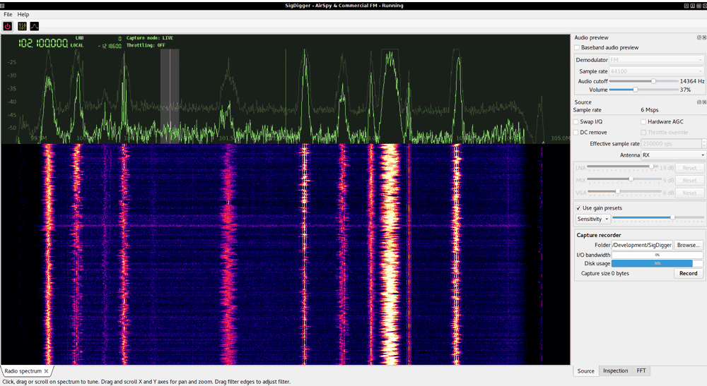
Recently a new open source Linux based SDR application called SigDigger was released by programmer BatchDrake (Gonzalo J. Carracedo). It is based on his own DSP libraries called Sigutils and Suscan which can take advantage of multi-core CPUs. SigDigger also makes use of the SoapySDR interface, so it is compatible with almost all software defined radios including the RTL-SDR.
SigDigger Screenshot
Like other general purpose SDR applications, SigDigger has your typical AM/FM/LSB/USB demodulation and audio playback features. However, it also has some key additional features that make it worth taking a look at if you're interested in reverse engineering, or taking a closer look at digital signals. The features include:
Both realtime and replay analysis modes
Analog audio playback (AM, FM, LSB and USB)
Baseband recording (full spectrum and per-channel)
Per-device gain presents
Dynamic spectrum browsing
ASK, FSK and PSK inspection
Gradient-descent SNR calculation
Different spectrum sources (cyclostarionary analysis, signal power…)
Symbol recording and visualization
Transition analysis
Planned features already implemented and just waiting to be exposed to the UI:
Symbol tagging (correspondence between symbols and groups of bits)
Automatic symbol tagging guessing
Automatic convolutional code detection
Viterbi decoding
We note that while the UI looks like GQRX, it is not based on GQRX at all. Rather BatchDrake just liked the minimal UI of GQRX. Also unlike GQRX, SigDigger is not based on GNU Radio, so it may be a bit more efficient and lightweight.
Below we've embedded a video that BatchDrake uploaded his YouTube channel which demonstrates SigDigger being used to inspect a PSK channel.
Using SigDigger to inspect a PSK channel
This software looks great, and we think it deserves some serious attention and testing, so check it out on the GitHub. Binary releases are also available, although BatchDrake notes that they are minimally tested, for x64 Linux only, and preferably for Debian-like distros. Alternatively, it can be installed from source, after installing the Sigutils and Suscan DSP library dependencies.
GOES 16/17 and GK-2A are geosynchronous weather satellites that transmit high resolution weather images and data. In particular they are far enough away from the earth to be able to take beautiful 'full disk' images which show the entirety of one side of the Earth. As these satellites are in a geosynchronous orbit, they can be counted on to be in the same position in the sky at all times, so no tracking hardware is required and images can be pulled down constantly throughout the day without having to wait for a polar orbiting satellite to pass over like you would with the NOAA APT or Russian Meteor satellites.
With a low cost WiFi grid dish antenna, LNA and RTL-SDR dongle, any home user within the footprint of one of these weather satellites can receive and decode live images directly from the sky. Setting up a station is overall not too difficult, but it can be a bit fiddly with a number of steps to complete. Below is our comprehensive guide. We'll show how to set up a self contained Raspberry Pi based system with goestools (free), as well as a guide for the Windows PC software XRIT decoder (US$125).
We've attempted to make the tutorial as newbie friendly as possible, but we do need to assume basic RF knowledge (know what antennas, SDRs, coaxial, adapters etc are), basic Linux competency for the goestools tutorial (using the terminal, using nano text editor), and basic Windows competency for the XRIT decoder tutorial (unzipping, editing text files, running programs).
A full disk false color image received directly from the GOES-17 satellite with an RTL-SDR. Click for the full size image (14MB).
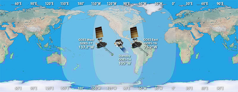
There are two fourth generation NOAA GOES satellites that are currently active, GOES-16 and GOES-17. These transmit HRIT signals, and also transmit shared data from the older third generation GOES 15, and Japanese Himiwari8 satellites. At the moment GOES-16 and GOES-17 are producing full disk images every 30 minutes, and close up shots of the USA every ~10 minutes. GOES-16 (aka GOES-R) and GOES-17 (aka GOES-S) are also known as GOES-EAST and GOES-WEST respectively. At least one of these satellites can be received from North/South America, Canada, Alaska/Hawaii, New Zealand, Eastern Australia and some pacific islands.
There is also the older generation GOES-15 and GOES-14 which have been placed in standby orbits. These transmit LRIT signals which provide images at a slower rate.
GOES 16/East and GOES 17/West Signal Footprint
There is also the Korean GK-2A (GEO-KOMPSAT-2A) satellite which is very similar to the GOES satellites. GK-2A covers countries like India, Asia, Australia, New Zealand and parts of Russia. Note that you may have previously heard of the COMS-1 satellite which used to cover this area. Since July 2019 COMS-1 was replaced by GK-2A. Unlike GOES, GK-2A images are encrypted. However it has been found that "sample" encryption keys found online in demo code work just fine.
GK-2A contains both LRIT and HRIT channels, but at the moment only the LRIT channel can be decoded with the currently available software. The LRIT channel sends full disk IR images every 10 minutes in 2200 x 2200 resolution. Compared to the 5424 x 5424 resolution GOES full disk images, this is smaller, but still large enough to be interesting.
Note that even if HRIT decoding is added by the current software, you would require an Airspy or other wideband SDR as the GK-2A HRIT signal bandwidth is 5 MHz. Also since the HRIT bandwidth is so wide, the signal strength is reduced, meaning that you'll need a larger dish. People who have received the HRIT signal note that a 3M+ sized dish seems to be required.
GK-21 (GEO-KOMPSAT-2A) Footprint
You might ask why bother receiving these satellite images directly, when you can get the exact same images from NOAA at https://www.star.nesdis.noaa.gov/GOES/index.php. Well, you might want to set up your own station to be independent from the internet, or you live in a remote location without internet, or maybe just for the fun and learning of it.
To set up a receiver for GOES 16/17 HRIT or GK-2A LRIT you'll need to purchase a dish antenna such as a cheap 2.4 GHz WiFi antenna, an RTL-SDR, GOES LNA, and a Raspberry Pi if using goestools, otherwise a Windows PC can be used. The total cost could be anywhere from $150 - $200 depending on what pieces you already have available.
Before we start the tutorial, you might want to use an augmented reality Android app like "Satellite-AR" to get a rough idea of where either GOES 16/17 or GK-2A (GEO-KOMPSAT-2A) is in your sky, and if receiving them is even feasible for your location. You'll need to find an area on your land where you can mount a small satellite dish with an unobstructed line of sight view to the satellite (no trees or buildings can be blocking the signal path). If the satellite is low on the horizon (below 25 deg elevation), then things get a little more difficult as you have more obstructions and a weaker signal. But it can still be done, and we're able to routinely get good results at 24.5 deg elevation.
Hardware Required
An RTL-SDR Blog V3 dongle. (US$21.95)
Some other RTL-SDRs will work too, but confirm that the dongle you purchase has a bias tee built in. (All RTL-SDR Blog V3 dongles have a bias tee). Alternatively, you can purchase an external bias tee.
Note that most of the cheapest generic RTL-SDRs do not work properly at 1.7 GHz due to overheating issues that we discovered can cause problems with reception above roughly 1.5 GHz. Only RTL-SDR Blog V3, E4000 and other dongles with cooling fixes will work.
An Airspy One can also be used with goestools on Linux and XRIT Decoder on Windows. An SDRplay unit can be used with XRIT Decoder on Windows only.
A low noise amplifier (LNA), preferably with filtering. (US$34.95) An LNA is absolutely required to receive the GOES signal. The LNA should ideally have a noise figure (NF) below 1 dB.
Optionally, adding a second LNA after the SAWbird can help improve reception too, but then you'll need to power the SAWbird directly. If powering directly be very careful and be aware that SAWBird products have a minor design flaw where if you use external power it will output power to the dongle side as well. This could destroy your RTL-SDR's ESD diode and other components if you do not use a DC blocking cap.
A 2.4 GHz WiFi parabolic grid dish antenna. (US$50 - US$100) 2.4 GHz is above our intended RX frequency of 1.7 GHz, but these antennas are confirmed to still work well. Note that for reception of satellites that are low on your horizon (below 25 deg), we recommend looking for a 1.9 GHz antenna instead as these work a bit better. However we have been able to confirm that with minor modifications we can still receive the signal decently at 24.5 deg elevation with a 2.4 GHz WiFi antenna.
A 2.4 GHz WiFi parabolic grid antenna - make sure you get the kind with the largest reflector (the grid dish part) possible. The right size is around 100cm x 60cm (39 x 24 in) or larger. Also ensure that it has a metal secondary reflector. Examples Products [1][2][3]
Alternatively, if you can find a similarly sized or larger 1.9 GHz antenna, then this will work even better. But these are typically much more expensive when compared to WiFi grid antennas and sometimes difficult to find.
Other circular satellite dishes can work too, but those typically don't come with their own feed as they're designed for LNBs. If using a circular dish you'd have to design and make your own feed. If this interests you, see Lucas' cantenna feed example as a reference.
If needed, you can improve reception by extending the parabolic grid dish reflector size with metal chicken mesh.
A mount for the parabolic dish. (US$39.99) This could be a portable antenna tripod, or a more permanent mast. Example product [1].
Coax adapter for the parabolic grid. (US$5.99) The grid antenna will typically come with an N-female connector. So look for an N-Male to SMA Male adapter, to be able to fit the RTL-SDRs SMA female input. Example product [1].
Low loss RG6 coax cable, or an active USB extension cable.
Either use low loss coax cable or a USB extension cable to get the LNA and/or RTL-SDR out to the antenna. An active USB cable will be required for longer USB runs. You may have to build a waterproof enclosure if mounting permanently outside.
To ensure good signal strength, the LNA must be connected right at the antenna - there should be as little coax as possible between the LNA and antenna.
We strongly recommend using as little coax as possible after the LNA too. The SAWbird LNA doesn't have enough gain to push the signal through long runs of coax. If you're forced to use long runs of coax, use a secondary LNA. Preferably use a USB extension cable to reduce coax runs.
A Raspberry Pi 3/4 + 8GB or larger SD card. (US$40 - US$100) Setting up the software on a Raspberry Pi 3/4 is the easiest way to create a permanent monitoring solution. Example product [1].
(Optional) You may want to have an external hard drive connected to the Pi for image storage as you'll be getting 1-2 GB of images a day.
(Optional) Weather proofing boxes.
If you're planning on running the system permanently, you'll want a water proof box to house your LNA and/or RTL-SDR.
(Optional) Additional Cooling
Avoid running the RTL-SDR or Raspberry Pi in direct sunlight, or in very hot areas. The RTL-SDR V3 has passive cooling, but if the RTL-SDR overheats from direct sunlight or a lack of surrounding airflow you will probably begin to see the viterbi error rates rising, and eventually failed reception. If you experience heat related issues, shield the SDR from direct heat, and/or use some sort of cooling system with a heatsink and fan. Even a small amount of airflow can help significantly.
Setting Up the Hardware and Modifying the Antenna
Overview of Hardware Connections and Pieces
Connect the SAWBird to the antenna, and then the RTL-SDR. Double check that you have the SAWBird the correct way around, with the "OUT" side connected to the RTL-SDR, and the "IN" side connected to the antenna. Keep the SAWBird as close to the antenna as possible. You can use a short run of coax between the SAWBird and RTL-SDR, but keep this to a minimum too. Instead of coax, use long active USB cables, or keep your Raspberry Pi close by.
GOES satellite signals are vertically polarized, so the secondary reflector and feed should be installed vertically, not horizontally.
For 2.4 GHz WiFi antennas, the secondary reflector might be curved. To optimize the reception for 1.7 GHz mount the secondary reflector concave side facing outwards.
You can improve the antennas performance at 1.7 GHz by adding a spacer to the secondary reflector so that it sits about 2.5 to 3.5 cm away from the primary reflector. Here is a video that demonstrates this idea. To mount the spacer you'll need to find a longer screw of the same size.
Modifications for 2.4 GHz WiFi Antennas to improve 1.7 GHz Reception
.
Pointing the Antenna
The antenna must be positioned outside. The signal is very weak so it will be very difficult to receive through a window.
Elevation: Angle up/down Azimuth: Angle left/right Polarization/LNB Skew: Rotation angle of the dish
Setting the Elevation and Azimuth
You'll need to point the grid antenna fairly accurately at the GOES satellite. If you are out by even 1-2 degrees, the signal will not be seen, or be weak. Use the website dishpointer.com to determine the Elevation and Azimuth that is required to point your dish, or simply take note of the line pointing towards the satellite and align the dish with features from your house. Note that on dishpointer GOES-17 is listed as 137.2W GOES-S (may change to GOES-17 in the future), and GOES-16 is listed as 75.2W GOES 16.
For now you can just point it roughly as we'll fine tune alignment later.
Dishpointer example. Line the dish up with the driveway corner.
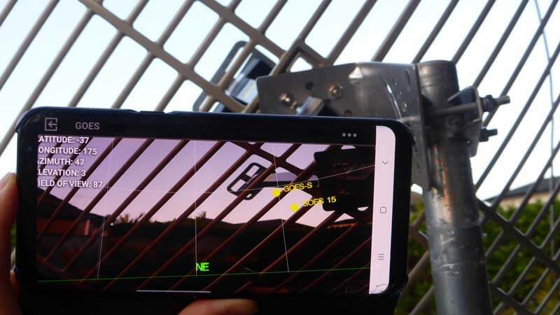
You can also use an augmented reality Android app like "Satellite-AR" to get a rough direction of the satellite. But this cannot be trusted for accuracy as the compasses on smartphones are often not very accurate. We recommend using a standard magnetic compass to help point by using the Azimuth (magn.) information from dishpointer.
Using the Satellite-AR Android App to check the rough direction of GOES-17.
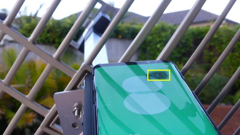
To determine the elevation you can use a bubble leveling tool, or an Android app like "Bubble Level".
NOTE: We may be slightly wrong on this polarization info as the polarization might also be dependent on the satellites's antenna oritentation. This info seems to hold true for GOES satellites, but not GK-2A. If any one can confirm, please let us know.
Once you have the Elevation and Azimuth of the dish approximately correct, you'll need to adjust the rotation (aka skew) of the dish in order to match the polarization of the satellite at your location. Dishpointer will tell you exactly what rotation angle to use, and in which direction, under the "LNB Skew" information.
If you are on the same longitude as the satellite your skew will be zero, and no rotation will be required. However, those further away on the longitude plane will require their dishes to be rotated. Most WiFi and 1.9 GHz grid dish antennas only allow you to rotate in 45 deg angle increments, so just choose the closest increment to what is given in dish finder.
In the image below Example 1 shows a user in California, pointing at GOES 16. Dishpointer shows that the required rotation is 42.2° CCW. So standing behind the antenna you would rotate the dish by 45° so that the left side is closer to the ground. Example 2 shows a user in New York pointing to GOES 16. Here the required rotation is almost zero, so no rotation is required. Keep the dish horizontal. In Example 3 the user in is Auckland, New Zealand pointing at GOES 17. Here the rotation is 44.6° CW, so the user would rotate the dish with the right side being lower.
Note that for GK-2A we found that the LNB skew given by dishpointer appears to be reversed in terms of the required rotation direction. We're not sure why, but may have something to do with the way the antenna is oriented on GK-2A.
Now that you have your dish pointed in the correct direction we'll need to fine tune the positioning to detect and maximize signal strength. When fine tuning the alignment of the dish you'll need to run a program like SDR#, and keep an eye on the spectrum and waterfall while making fine adjustments to your dish. If you can't see your PC screen while positioning the antenna, it will be very difficult to confirm and tune reception.
To make it easier if you don't have a laptop, install the Teamviewer application (or any alternative like VNC) on your desktop PC, and run SDR# with the dongle and LNA connected to the antenna. Then view the PC's screen on your mobile device using the Teamviewer App, and slowly move the dish around until you see the HRIT/LRIT signal. If using the RTL-SDR V3 make sure that you activate the bias tee first using the bias tee software (see Feature 2 on the V3 guide).
Try to get the signal as strong as you can, but do not worry too much about ultra fine tuning. Later when running the software we will optimize the reception even further using the viterbi error correction rate produced by the decoder software.
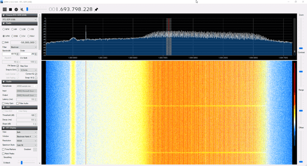
The image below shows what reception of a GOES 16/17 HRIT signal looks like. The large bump on the right is the HRIT signal which contains all the weather image data. The narrowband signal on the left is EMWIN, which contains simple text data and simple weather fax type images.
What GOES-17 looks like in SDR# on an RTL-SDRChecking GOES Reception Remotely via Teamviewer
Note that there are sometimes brief periods of a few minutes where the GOES signal is idle. During this time the HRIT signal level will be a bit lower.
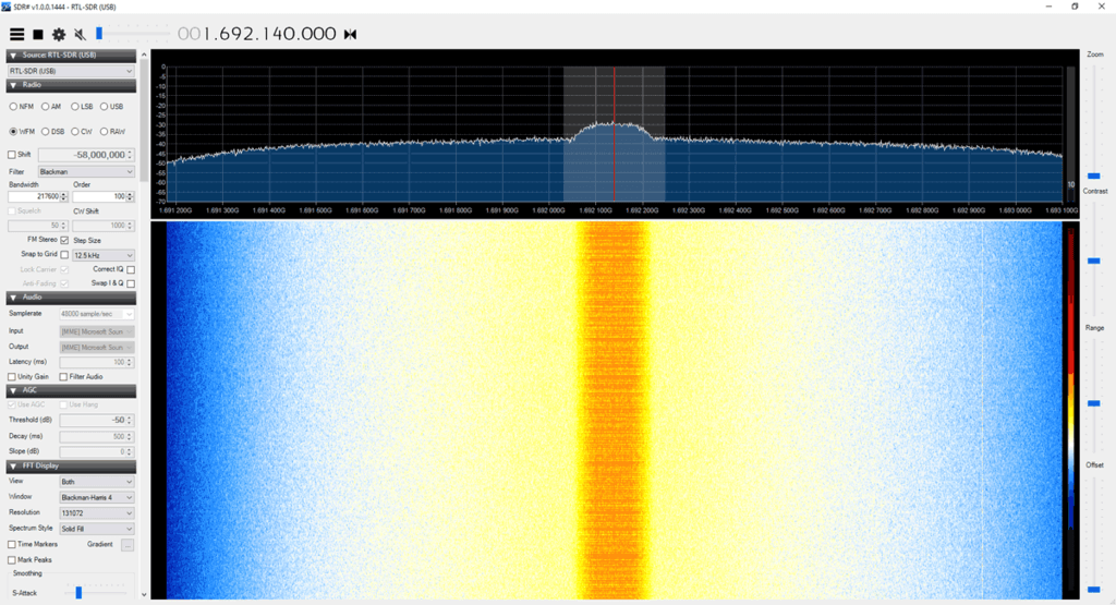
The image below shows that the GK-2A LRIT signal looks like.
GK-2A LRIT Signal
Sun Interference Note: During the day time while the sun is up reception signal strength can be reduced, sometimes even resulting in no reception at all. If you cannot find the signal during the day, try again later at night after sundown. Interference appears to be the worst when the sun is behind the satellite.
When the sun is behind the satellite, we cannot receive the signal at all.
Raspberry Pi goestools Linux Software Install and Setup
For the Raspberry Pi we will use the goestools software suite which decodes and generates images for us. Goestools is made for Linux, but it might be possible to compile and run on Windows/MacOS too, although we're unaware of any successful attempts. The easiest way to set it up is to install it on a cheap Raspberry Pi 3/4.
Connect the Pi to a monitor, log in with username: pi and password: raspberry, then run "sudo raspi-config" and set up your WiFi connection.
If using an Ethernet cable you do not need to set up WiFi.
Find the IP Address of the Pi either via Method A or B
Using a monitor, open a terminal on the Pi and find it's IP address by using the command "ip addr" without quotes. Or,
Open your network routers' configuration page on any PC, and search the settings for a list of connected devices. You should be able to see the Raspberry Pi listed there, with it's IP address.
Now you should connect to your Pi from a PC on the same network using any SSH software such as PuTTy.
At this point we recommend following the excellent goesrecv software installation guidelines written by Aleksey Smolenchuk (lxe). Go through steps 1 - 6. It is a simple matter of copy and pasting the commands into the SSH terminal.
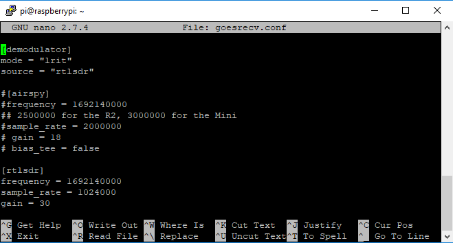
However, on step 6 of Aleksey's guide, we recommend changing the sample_rate to 2000000. We've found that higher sample rates often cause goesrecv to require multiple restarts in order to get a lock on the frequency. Also if you're using an RTL-SDR V3 enable the bias tee and increase the gain to 30:
sample_rate = 2000000
gain = 30
bias_tee = true
Running the Software and Fine Tuning the Antenna
Later we will create a script that automatically runs the software on boot. However, for now let's first test it.
To run the software open two separate SSH terminals on your main PC using PuTTy or a similar SSH terminal program. Connect to the Raspberry Pi's IP address, port: 2222 with SSH. Log into the Pi with the default username/password: pi/raspberry. In the first terminal run the command:
goesrecv -v -i 1 -c ~/goesrecv.conf
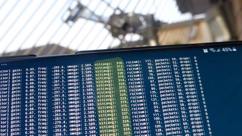
At this point you'll see a bunch of data begin to scroll by. The important thing to look at is the "vit(avg) and "drops" data. You should be seeing zero drops, and a vit(avg) of below 500, and ideally below 400. If you are seeing higher vit(avg) values and drops, you must realign and improve your dish antenna's reception. If you're getting a vit(avg) of around 400 - 600 you may be able to proceed, but some images may be lost or incomplete if you are seeing frequent drops. Anything above 600 and you probably won't be able to get any images.
Signal Optimization TIP: To further optimize the signal, install an SSH terminal like "JuiceSSH" on your mobile device. Run the above goesrecv command on your mobile, and adjust the antenna until the vit(avg) reading is as low as possible. You may need to restart goesrecv after a large adjustment for it to get a better lock on the frequency.
Remotely checking vit(avg) with JuiceSSH on Android.
Finally, if you have vit(avg) below 500 and are seeing zero drops, run the following command in the second PuTTy window.
At this point images will begin to download. Check back in 15 minutes and see what you've received. All images are written to the folder specified by the --out flag, in this case /home/pi/goes.
During testing you can easily transfer files out of the Pi to a Windows machine on the same network using a program called WinSCP. When starting WinSCP, simply select "New Site", choose the SCP file protocol and enter the Pi's IP address. You can then browse the Pi's directories, and download the image files from the folders generated in the home directory. But this is slow and time consuming, so we recommend using a more automated solution explained further below.
Also, if you wanted to, you could run goesproc on another Linux PC on your network and have the images generated on that machine. To do that, run goesproc with the Raspberry Pi's IP address in the --subscribe flag on the networked machine.
Browsing Images in a Web Browser
Note that we've had issues with Mediaweb crashing and being very slow when generating thumbnails, so we generally recommend that you use syncthing (shown below) instead.
An easier way to view the downloaded images is to install a simple folder web server like "Mediaweb" which will allow you to browse your received images on a web browser over a network connection.
Install the software using the instructions on the mediaweb Git. When installing be sure to choose /home/pi/goes as the default directory. Once installed Mediaweb will run in the background continually even after rebooting. So you can always browse your images.
Once mediaweb is installed and running, you can then browse to PI_IP_ADDR:9834 on any device connected to the same network as the Pi, and you'll be able to see the currently created folders and images (where PI_IP_ADDR is the IP Address of your Raspberry Pi).
Note that you might want to enable the thumbnail cache in /etc/mediaweb.conf, too. Remember to restart mediaweb after by using "sudo systemctl restart mediaweb".
Automatically Transferring Images to your Windows/Other Main PC
Syncthing is a program that you can use to automatically copy and sync your goes image folder with your main Windows/Mac/etc PC on the same network.
Syncthing is configured via a web interface, with default IP address of 127.0.0.1 (localhost). As we're running Raspbian Lite, we don't have a GUI and therefore can't run a web browser on the Pi. So we'll need to open the browser based configuration GUI on a networked PC. To do this we need to set the IP address of the GUI to the Pi's local network address. Edit the syncthing config, and under the <gui> entry, change the <address> value to 0.0.0.0 which will allow you to connect to the Pi's IP Address.
sudo nano /home/pi/.config/syncthing/config.xml
Syncthing config, set IP to 0.0.0.0
Save and exit with CTRL+X, Y.
Next, run "syncthing" on the command line.
Now on your main PC, open a web browser and browse to PI_IP_ADDR:8384 to open the syncthing GUI for the Raspberry Pi.
On your main PC, download, install and run the Windows version of syncthing. This will automatically open up a browser with the GUI for the Windows syncthing instance. Click on "Add Remote Device". It should be able to find the Raspberry Pi automatically, and you can double check the device ID by going to Actions->Show ID in the Raspberry Pi GUI. In the Windows GUI, simply click on the device ID, and click on Save.
Within a few seconds/minutes, the Raspberry Pi GUI should pop up with a "New Device" alert. Click on Add Device -> Save.
Still within the Raspberry PI GUI click on Add Folder. Set the folder path to /home/pi/goes, and set the label to "GOES Images". Leave the Folder ID default. Go into the "Sharing" tab, and enable sharing for your Windows machine. Click on Save.
After a few seconds/minute or two, the Windows GUI web interface should pop up with a "New Folder" alert. Click on "Add", then under "Folder Path" set where you want the image files to be copied to. Then click on save.
Wait a couple of minutes, and then it should begin syncing.
Run goesrecv, goesproc and syncthing Automatically on Boot
At the moment goesrec, goesproc and syncthing all need to be started manually whenever the Pi is rebooted. It would be better to create a system that automatically runs goesrecv, goesproc and syncthing when the Pi is booted. Then there is no need to keep an SSH terminal open and manually start the receiver and decoder whenever the Pi is rebooted.
First create two startup scripts called startgoesrecv.sh and startgoesproc.sh in your home directory.
Next create a system service that will load the script on boot, after the network service has already been loaded. We are creating two services instead of one, because we need goesrecv to start as root in order to be able to open the RTL-SDRs, and goesproc to start as user pi to make accessing the files easier later on. Also Syncthing cannot be run as root.
# Create the service to start goesrecv

sudo nano /etc/systemd/system/startgoesrecv.service

# Copy and paste the following

[Unit]
Description=Start GOES receiver after network is loaded
After=network.target
[Service]
User=root
Group=root
Type=oneshot
ExecStart=/home/pi/startgoesrecv.sh
[Install]
WantedBy=multi-user.target

# Create the service to start goesproc

sudo nano /etc/systemd/system/startgoesproc.service

# Copy and paste the following
[Unit] Description=Start GOES processor after network is loaded as user pi
After=network.target
[Service]
User=pi
Group=pi
Type=oneshot
ExecStart=/home/pi/startgoesrecv.sh
[Install] WantedBy=multi-user.target

# Create the service to start synthing
sudo nano /etc/systemd/system/startsyncthing.service

# Copy and paste the following
[Unit] Description=Start syncthing after network is loaded as user pi
After=network.target
[Service]
User=pi
Group=pi
Type=oneshot
ExecStart=/usr/bin/syncthing
[Install]
WantedBy=multi-user.target
Note that if you plan on making this a permanent station, it would be wise to connect a large external hard drive to your Pi, and save images to there. In that case you'd change the --out flag in the startgoesproc.sh to the path of the harddrive.
(Untested Idea) Even with a hard drive, you might also want to remove files and folders older than ~30 days or so to avoid running out of space. GOES16/17 transmit about 2GB of data a day so storage can run out fast. (Adjust +30 in the script below to how many number of days of images you want to keep)
The easiest way that we found was to use an online service like https://gifmaker.me. Pieterns goestools guide shows an offline Linux method involving Imagemagick, but we found it too slow to run on a Pi 3.
Then to share upload to an efficient GIF sharing site like gfycat.com.
Below is a GIF of half a day of GOES 17 false color full disk images that come in every 30 minutes.
Below is a short GIF from GK-2A with 10 minute interval images.
Raspberry Pi GK-2A goestools Tutorial
Please note that GK-2A decoding is still in it's infancy, and the decoder is still being worked on by @sam210723. He is frequently updating his modified version of goestools and his xrit-rx software for GK-2A decoding.
First install the modified goestools for Gk-2A version at https://github.com/sam210723/goestools. Compilation instructions are on the page BUT we DO NOT recommendusing the apt-get install librtlsdr-dev line in his instructions, as this will most likely install an older version without bias tee support. Instead, install librtlsdr from source as explained in Aleksei's guide. If you already installed the original goestools before then you will already have the correct librtlsdr installed. But note that running sudo make install will overwrite the original GOES goestools version. If you prefer you can just run the GK-2A goesrecv program from the build/src/goesrecv folder and not run sudo make install.
Next edit the goesrecv.conf file that you copied over with "nano goesrecv.conf". If you're using an Airspy, the conf file should already be ready, but you may want to edit it to activate the bias tee. If using an RTL-SDR, change the "source" to "rtlsdr", comment out the [airspy] settings by putting a "#" in front of them, and remove the "#" from the [rtlsdr] lines. Set the gain to 30, and bias_tee to true. CTRL+X, Y to save and exit.
Editing the goesrecv.conf file for RTL-SDR GK-2A reception.
Install xrit-rx
XRIT-RX takes the place of goesproc. First we need to download the encryption key.
You'll now have a file EncryptionKeyMessage_001F2904C905.bin.dec stored inside the xrit-rx folder. Now edit the xrit-rx.ini file with nano, and set the "keys = EncryptionKeyMessage_001F2904C905.bin.dec"
Set key file in xrit-rx.ini
Finally, open two terminal windows in PuTTy. In terminal one run the following, and confirm that you get a low vit(avg) rate, and no drops.
goesrecv -i 1 -c goesrecv.conf
In the second terminal window run the following and it will automatically begin creating LRIT files.
sh xrit-rx.sh
In order to create images from the LRIT files you need to periodically run the lrit-img.py program found in the tools folder. Once run the full disk images will be produced in the FD folder.
# Install a dependency
pip3 install pillow

# Browse to the current date
cd ~/xrit-rx/received/LRIT/20190819

# Run the program on the "FD" folder
python3 ~/xrit-rx/tools/lrit-img.py FD
Like with the standard goestools setup, you could now make these programs run on boot with systemd, and set up syncthing. You could probably also create a crontab entry to periodically run lrit-img.py.
Windows XRIT Decoder Tutorial
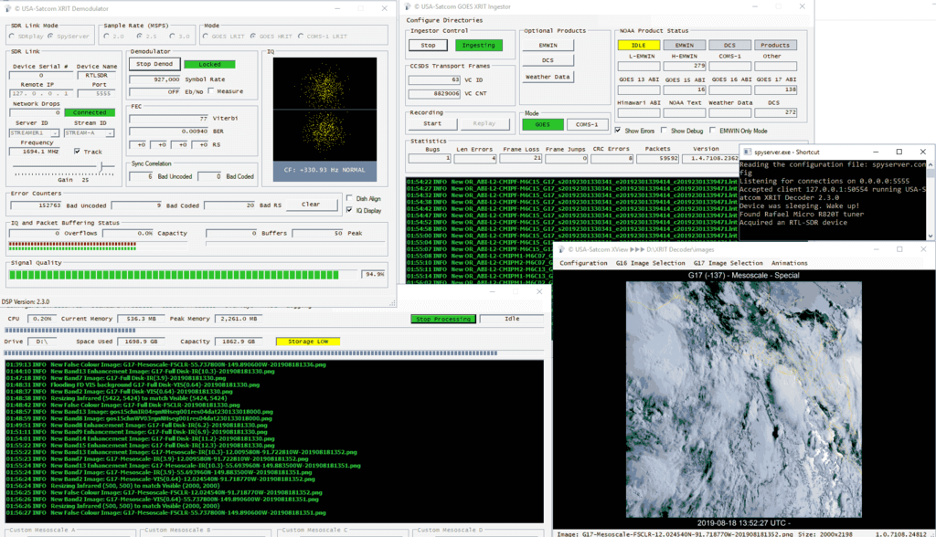
If you instead prefer to use Windows software, USA-Satcom (Joe) has a decoder called "XRIT Decoder". Due to certain libraries used, it is not free and is available for a price of USD $125. The price includes free future updates and access to a private groups.io forum for support and downloads.
An additional US$25 gets you an option piece of software called "XView" which is a viewer that allows you to view and filter images as they arrive. This is useful if you're creating some sort of live display. XView also has an animation feature that allows you to easily create weather movies.
XRIT-Decoder can decode GOES LRIT and HRIT data. It also appears to be somewhat compatible with GK-2A LRIT at the moment, and this is set to be improved in the future. It is compatible with the RTL-SDR, Airspy and SDRplay software defined radios.
In order to purchase XRIT-Decider you must contact him directly by email. You can also request a 30-day demo. After purchasing or requesting a demo USA-Satcom will send you activation and usage instructions.
XRIT Decoder SpyServer Setup
Note that if you are using an SDRplay SDR, you can skip this step.
For RTL-SDR and Airspy SDRs, XRIT Decoder relies on SpyServer from SDR# to provide data. SpyServer is a remote server application that supports the RTL-SDR and Airspy products. It's a part of the SDR# software package and can be downloaded from www.airspy.com.
SpyServer runs on Linux, Windows and ARM single board PCs like the Raspberry Pi. So if you wanted to you could set up a remote SpyServer on a Raspberry Pi connected directly to the antenna, and decode the data remotely on your Windows PC with XRIT Decoder.
Turn on the bias tee.
If using an RTL-SDR V3, run the V3 bias tee software and turn ON the bias tee.
If using an Airspy, edit spyserver.config with a text editor and uncomment (remove the preceeding #) the "enable_bias_tee" option in spyserver.config, and set it to '1'.
Start the SpyServer by double clicking on spyserver.exe, or running it from the command line in Linux. The default config is fine for RTL-SDRs - just remember to activate the bias tee first in step 1.
Starting and Running XRIT Decoder
After purchasing XRIT Decoder, USA-Satcom will send you usage instructions that we won't repeat here. The basic steps are to run xrit_decoder.exe, select the SDR, sample rate and mode (LRIT/HRIT), then click on Start Demod. (For GK-2A select COMS-1 LRIT). You can then adjust the gain, and check the Viterbi rate. Like with the initial antenna setup, you can then use Teamviewer and the "Dish Align" feature in XRIT Decoder to fine tune your dish for the lowest Viterbi error rate. USA-Satcom recommends a viterbi rate of below 100, but we've found that under 400 still gives decent results.
Once your viterbi is optimized, go to the GOES XRIT Ingestor screen and click Start. Now you can open xrit_file_manager.exe, and click Start Processing in that window. Over time images will be stored in the "images" folder within the XRIT Decoder folder.
Finally, if you purchased XView, open xview.exe, and set the image path if necessary. Over time the last downloaded image will be displayed.
XRIT Decoder Screens
Example Images that You'll Receive from GOES 16/17 and GK-2A
GOES17 Full Disk False Color. Click for the full size image (14MB)Himawari 8 IR Full Disk Relay Image (Infrared) Received from GOES 17GOES 16 Full Disk Relay Received from GOES 17GK-2A LRIT IR Full Disk ImageGOES17 USA ImageNOAA AnalysisNOAA AnalysisNOAA Analysis