The RTL-SDR can be used to receive, decode and plot Global Positioning System (GPS) data in real time. To do this the RTL-SDR must be connected to a GPS antenna.
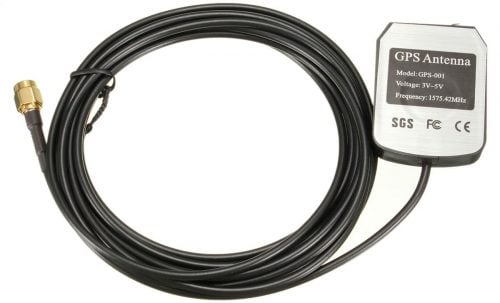
Extremely cheap $5 or less active GPS antennas with SMA connectors can be found on eBay, Amazon or Aliexpress. These GPS antennas contain a small ceramic patch antenna, a low noise amplifier and a GPS filter. In order to power the LNA in the antenna, you’ll need to have an RTL-SDR with bias tee. Our RTL-SDR.com V3 dongles have this feature built in, but if you don’t have a V3 you could also use a homebrew 5V external bias tee module or hack it into a standard RTL-SDR if you desired.
Also note that most standard R820T/2 RTL-SDRs fail to receive after a few minutes at frequencies above about 1.3 GHz due to heat issues. Our RTL-SDR.com V3 dongles don’t have this problem in most climates thanks to the metal case cooling and improved thermal design on the PCB. If you experience this problem it can also be alleviated by using the special L-Band RTL-SDR drivers.
The main GPS frequency is 1.575420 GHz, but most of this signal is very weak and below the noise floor. If you were try to view the spectrum of GPS in SDR# you will find that you won’t see much other than perhaps a very weak hump. Only through clever signal processing is such a weak signal actually recovered. Below we show screenshots of the GPS spectrum as seen by an RTL-SDR and more wideband Airspy R2 SDR.


The following tutorial shows how to receive and decode GPS signals and get a coordinate on a map of your location, using only an RTL-SDR dongle (with bias tee) and GPS antenna. This tutorial is based heavily on Philip Hahn’s blog post at sdrgps.blogspot.com/2015/12/first-proof-of-concept-gps-fix-in.html.
- Download GNSS-SDRLIB from github.com/taroz/GNSS-SDRLIB. On GitHub click on the green “Clone or download” button on the right and then click “Download ZIP”. Extract the zip file into a convenient folder on your PC. If you want to use the modified L-band drivers, copy the modified rtlsdr.dll into the the bin folder.
- Download the latest version of RTK-NAVI from rtklib.com. If you like, you can also try their beta version at github.com/tomojitakasu/RTKLIB_bin/tree/rtklib_2.4.3. Extract the zip into a convenient folder on your PC.
- Make sure your RTL-SDR is plugged in, and that the bias tee has been activated (V3 software for activating the bias tee, see feature 2).
- In the GNSS-SDRLIB folder, open gnss-sdrgui.exe. This will be stored in the bin subfolder.
- Now set the following parameters:
- Change the Input Type to RTL-SDR
- Place a check next to RTCM MSM , and set the Port to 9999.
- Ensure that “Output Interval” is set to 10Hz.
- Ensure that “Plot Acquisition” and “Plot Tracking” are both checked.
- Under “MISC” optionally enter your approximate latitude and longitude to help with getting an initial lock..
- Under the GPS, GLONASS and Galileo headings ensure that the “ALL”
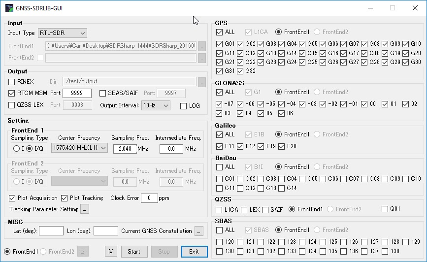
- Press Start. A bunch of command windows will begin opening and closing for a few seconds. After that, a bunch of gnuplot graph windows will open up. These can be ignored.
- Next go to the extracted RTK-NAVI folder, and enter the bin directory. Open the rtlnavi.exe file.
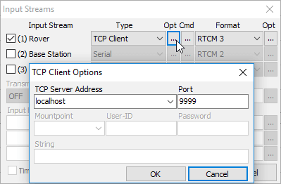
- Click on the “I” button in the upper right region.
- Place a check mark next to (1) Rover, and change the “Type” to TCP Client, and the “Format” to RTCM3. Click on the button with three dots under the leftmost “Opt” and set the “TCP Server Address” to localhost, and the “Port” to 9999. Press the OK button to exit the two windows.
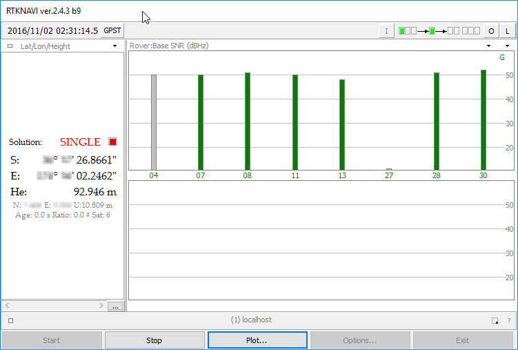
- Now press Start in RTK-NAVI.
- You should now see several bars in the top graph. These bars show GPS signal strengths for satellites. After a short time you should see a solution in the left panel which will be your current coordinates. If no solution ever comes, try respositioning your GPS antenna for a better view of the sky, and double checking that the bias tee is activated. Sometimes simply restarting GNSS-SDRLIB can fix no solution being found.
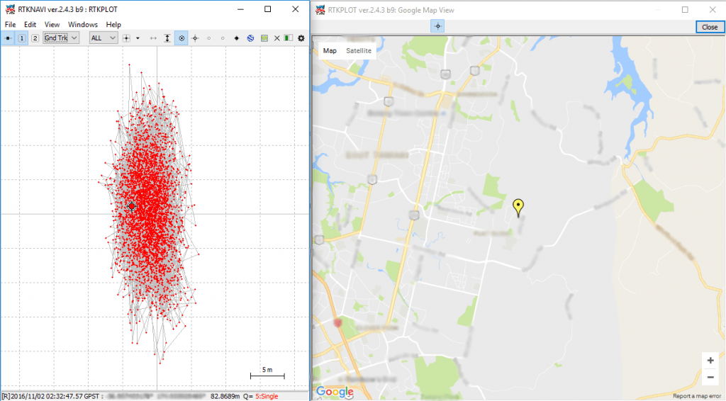
- In RTK-NAVI click on the “Plot” button. This will open a positional plot of the recorded coordinates. To view your position on a Google map, click View → Google Map View. If everything is working correctly you should now be seeing an accurate marker of your current location.
The post RTL-SDR Tutorial: GPS Decoding and Plotting appeared first on rtl-sdr.com.